

Wireless control
This walk through describes a cheap way to create a wireless controller for a robot. It is not a ready-to-go manual, but a proof of concept. It's how I did it and succeeded. And how I failed a bit. I will warn you for the tricky parts.
What's in a name
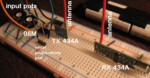
Many vendors sell cheap radio modems for wireless serial communication. I successfully used these and these from Sparkfun as a remote controller for my robots. They cost me around $5 per unit. They come in different flavours. Make sure to match transmitter type with receiver type.
Unfortunately, there is not a good generic name for these modules. So your vendor might be offering the exact same units under a different name. Inversely, you might find units with similar names or claims, that are very different from the ones I am describing here.
Let me break this down, LMR style: Idea, Mechanics, Electronics, Programming.
Idea
The intention is to transport individual bytes from transmitter to receiver. TX to RX. There is no return path. A second RX will receive the same signal. A second TX will interfere with it. If you need true bi-directional communication, look for Xbee. They are more expensive, but take a lot of work out of your hands. And they are bi-directional.
Mechanics
My proof-of-concept is for a robot (a 6x6 Wild Thumper chassis) with differential drive. The controls are "tank style". This means that my controller has two "levers", corresponding to the port side (left) and starboard side (right) of the vehicle. The motors are reversible. Each lever controls 16 speeds: 8 forward and 8 reversed. The two speeds in the center count as "dead band" between the two directions. That's where the wheels stop.
Electronics
The transmitter has two potmeters, one for each lever. The value is arbitrary. I had some 500 kOhm of the right type lying around. Don't go lower that 10 kOhm or your joysticks will drain your battery. The transmitter gives better range when you feed it a higher voltage. They can take up to 12 V. I went with ca 8 V. The Picaxe 08M microcontroller needs 5 V. That's where the low dropout voltage regulator LM2940CT comes in.
Additional components: power indicating LED, decoupling/buffering capacitor (bigger is better) and a few connectors/header pins. feel free to throw in an extra 1 nF decoupling capacitor near the Picaxe.
The transmitter unit slots into the four ping female connector (the schematic show one pin too many). Power is supplied by (6) AA NiMh cells. The antenna is a 1/4 wavelength piece of wire. For 434 MHz that means 17 cm or 6.7 inch.
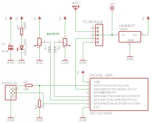
The receiver is simpler. Power is supplied from the bot's main brain. The header expects Data/V+/GND. The receiver unit has two sets of four pins. Aagain, the schematic shows five pin female headers (I was too lazy to find a better symbol). The decoupling capacitor C1 is placed as close to the MCU's power pins as possible. The extra LED (red) serves as an indicator for "bad data".

The download circuit for connecting the picaxe to the programmer (your computer) is a text book circuit. A voltage divider (22k/10k) to reduce the 12 V signals coming from the PC to ca 4 V. For the Picaxes, I used the generic symbol PIC12F683P. That's why the pin labels look funny.
Programming
These radio modules do not transmit until you send some serial signals to the TX data pin. The transmission needs to get going before you can reliably transport your byte(s). The best way to do this is to send a series of zeroes and ones. This is called a preamble. Binary %01010101 corresponds to decimal 85 (or hex $55). So whatever we send out, we will always begin with transmitting 85.
The receiver uses the plain old serin command. This Picaxe command waits indefinitely for serial data to arrive. The serial communication between radio unit and Picaxe is not buffered. You snooze, you loose.
The radio RX unit will not send serial data to the Picaxe unless it is sure there is clean data coming in. Sometimes that includes the preamble, but not always. My project uses just a single byte to transmit the two joystick values. For error detection, I will send the value twice, immediately after the preamble:
serout pin_radio, N4800_8, (85, bytevalue, bytevalue).
The receiver either receives a preamble, or misses it. Only when a good preamble was decoded, will we move on to receive the following two bytes. And only when those two are identical, will we accept them as valid commands for the motors.
[This walk through is probably not complete yet. I only just rediscovered this node on 22 march 2011. It had been in draft for months! I guess I wanted to write some more and lost track. Such is life. Feel free to ask for additions in the comments!]