I am new to the forum. My son (10 years) has build the robot as described in the 'start' page. I halped him during the process and the connection with the computer. We do not understand how to make the sensor working. The servo turn with the basic parameters and wheels turn as well. As an example we tried to imput in the Picaxe software the following:
main:
readadc 0, b0
debug
goto main
and when the hand is put in front of the senson there are some numbers changing on the debug window. However we tried to transfer the whole script in the start page that starts with the following string:
Symbol dangerlevel = 70 ' how far away should thing be, before we react?
and ends with:
return
but only the wheels move in forward. We checked lots of time the connections as described in the images in the start page. The only difference with the sensor are the colors of the wires i.e. black yellow and red in stead of black white and red. Thus, we connected the yellow in the middle and kept the red external (edde of the board) and the black internal (on the same plane of the image in the start page).
Any suggestion is apreciated (we worked on this all the weeked!),
In what range are the numbers that are changing in the debug window?
And do they change up or down when you place your hand in front of the sensor?
Also, on your jst connector or the jumper wires you are using to connect to the sensor, if you look the sensor “in the eyes” on which side is which colour wire?
I labeled the pins based on the colors you said your wires were colored. Notice the Yellow wire will be on the outside at the sensor and as you showed in the middle at the PICAXE board. I believe you only grounded the sensor out pin, so, you should not have done any damage.
It is fantastic to read that It is fantastic to read that you support your 10 year old son on the quest to build a robot. Many kids do not get the parental support that seems to be very natural to you. So go on and if you bump into the next problem LMR can support you two again.
Here is the set up: it is OK? Sensor still not responding.
Hi All,
Many, many thanks again for you support. Here are the images of the work done (my son can’t sleep at night looking forward to have this robot completaly alive!).
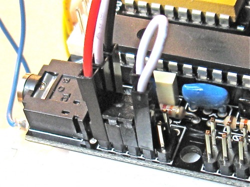
The followingare the wires for the sensor (you may not seen very well the black but it is connected to the opposite side of the red, yellow in between):
The following is for the servo. I assume the connections are OK since the servo is alive:
The following is for the sensor:
I have not had the change to test it with a voltmeter (I am quite incopetent here). I will try to do it today.
Please have a look if the connctions are all right.
This all looks correct to me, anyone else who can spot anything that looks wrong?
Would you be able to tell us what range the numbers you are getting are in (i.e. do they go from 100-1000, or 30-600, or something entirely different)? and how they change when you put a hand, let’s say within 15 centimeters, of the sensor?