I’m looking to build a pair of wings that have the same degree’s of freedom that a bird has. Just about every animatronic wing build I’ve seen on the internet so far seem to be limited to the same degrees of freedom (not sure what number of DOF this would be considered), fanning and closing open and flapping. The original build that inspired me to attempt one of my own were these wings created by the user ■■■■■■■■■ who posted various pictures of the building process and also has some videos showcasing the movement such as this one:
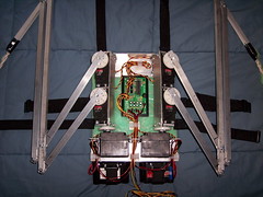
As you can see the movement is very realistic but the wings lack the ability to fold at the middle of the arm that you see during the upstroke of a birds flap. The reason I believe this additional degree of freedom isn’t used is due to additional complexity during the build as you would have to add a servo or some other part which would interfere with the commonly used construction of straight pipes/arms which when fanned out extend the arm and likewise retract when closed. Most wings seem to use the double arm skeleton as you can see in this photo:
I was curious to why the seemingly universal tubed skeleton layout is used when building such wings? I’m guessing that you need both pipes for them to extend or retract? I’d like to make a more streamlined build with potentially just one tube per joint to keep the build as streamlined and lightweight as possible, I’m thinking an additional servo would be need in the middle of the arm for the wing to fold during the upstroke. I’m wondering if streamlining the movements to servos over the motors used in Busitaka’s wings to something like these wings from the user Skaros444 would be more optimal:
I’m thinking I’d only need one servo rather than the additional two for fanning the wings out while the bottom most servo would be used for flapping. I’m still a bit confused on how I’d add the mid arm servo to allow the wing to fold without adding a servo for each joint seeing as how the normal strategy is to allow the wing to naturally extend/retract simply by extending the wing outwards. Any ideas on how to obtain this increased DOF while streamling the build?
It’s all a question of mechanical design and linkages. We have seen many attempts at wings using various different designs (the video you link to has many others on the side bar). If you want an extra degree of freedom mid-wing, you’ll need to add another joint and actuator. Simulating the design in CAD would help. One way to avoid using many servos is to use a central DC linear actuator. robotshop.com/en/actuators.html
Yeah it seems like unexplored territory for the most part with each iteration of design being unique as each creator aims for a particular style for their purposes. I did in fact go through almost every video on the sidebar of each video and wasn’t able to find one with the mid wing folding degree of freedom I was referring to though there were many interesting designs.
The actuator is a great idea and I’ve seen it implemented in some wing designs though not for the mid wing degree of freedom but rather to help extend the wings out such as in this wing design by Alexis Noriega:
I’m looking to create a pair of animatronic cosplay wings and was wondering what the smallest servo’s combined with servoblocks (if necessary) would be to sufficiently extend and flap the wings in a realistic motion? Many of the animatronic cosplay wing projects I see use actuators which seem effective but are large and above all expensive. I was thinking of using aluminum tube shafting combined with actobiotic modular parts to create the ideal wing frame then use 2 servos, 4 in total, for each wing to allow flapping and also to extend the wing. I’m assuming I can just combine the servos together in the right configuration to create the movement range I need then bolt them to a actobiotic pattern plate, and then connect the tubing to the servos.
So far I haven’t found the most ideal part to allow the tubes to pivot at the joints so that the wings could extend and retract, does anyone have any ideas on what might achieve an ideal pivoting effect? Most articulating cosplay wings appear to use roughly the same wing frame layout with the tubes, or whatever structural component they use for the arms is, arranged in a way that will automatically extend the wings once the main innermost wing arm starts to extend out. Does anyone know what the best wing frame layout would be with the servo setup I’m thinking of?
If you want something small, then you need to do a complete torque balance (i.e. “do the math”). Small servos generally have very low torque, so even the smallest of weight at the end of the wings will add significant torque.
Building wings is not something common to hobby robotics - it’s really specific to cosplay.
I’ve been rigorously researching on how to make a servo based wing arm and really feel the robotic arm style layout would be ideal to achieve the most accurate DOF to mimic a birds range of motion. Here is a video of the degrees of freedom I’m aiming for:
As you can see the wings can fan out/in, flap, and rotate up/down. I’d like to be able to add an additional degree of freedom on the end of the humerus (assuming this is where you would put a servo to achieve this DOF) to be able to fold the wings in front of you like a shield like this:
Really what I’m trying to find out is what the best components would be to create this project, I was browsing through Actobiotic’s modular parts trying to picture how it would be setup in my head, then I came across Lynxmotion parts and now I’m not sure which would yield a more streamlined and superior build. I spoke with some tech’s from Servocity, and have been trying to contact others to get their opinions on this build, who recommended actuators over servos for such a project, I’ve seen actuators in various cosplay wings such as these:
Actuators seem quite a bit more expensive than a servo setup though the tech I spoke to said the servo setup could become more costly which I presumed they meant if I used an overabundance of servos compared to an actuator. Actuators seem to just fan out/in the wings and that’s it, couldn’t a servo achieve the same thing? Any recommendations on streamlining the original wings I linked with modular robot parts from actobiotics/lynxmotion?
This is a wing design shared by a deviantart user but I can’t quite understand the workings of it, specifically the flapping gearbox which appears to utilize one dc motor connected to some arrangement of clamps which somehow turn the rods that the wing spars are connected to. I’m guessing that the clamps are setup in the opposing angles so that the single rotational action of the one motor results in symmetrical flapping of the wings?
The motors on the shoulders are easier to understand, they appear to use a worm gear connected to a dc motor to pull themselves up and down the stationary gear but I can’t be sure of this as to my understanding worm gears provide very slow movement but as you can see in the video below of this mechanism in action (they are the butterfly wings rather than the bird style wings (different mechanism) that the creator deviated to) the movement is quite fast.
Video of wings: youtube.com/watch?v=xg8j4OFy-ys&t=10m34s
Diagram of wings: ■■■■■■■■■■■■■■■■■■■■■■■■■■■■■■■■■■■■■■■■■■■■■■■■■■■■■■
This mechanism appears to use connecting joints to rotate both shafts at the same time in a symmetrical motion as can be seen in the video below, how exactly does it work? I’m a bit confused on how to build such a thing as the connecting pieces are not symmetrical themselves but rather at different angles which I’m sure is to make up for the single direction of the motors rotation? Can anyone explain this setup?


