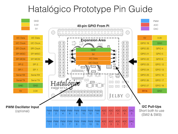
Prototype_Pinout.pdf (153754Bytes)
UPDATE 9/May/2015
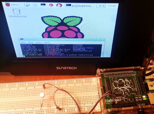
I have started to test my Hatalogico board with PWM control and it's promising. Please check here the details.
UPDATE 4/May/2015
Added:
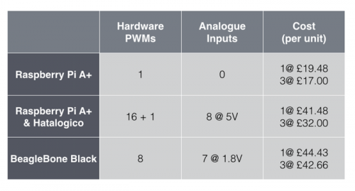
- comparison between Raspberry Pi + Hatalógico vs BeagleBone Black: related to PWMs and Analogue I/O
- Pinout detailed
UPDATE 1/May/2015
I fell all you saw also the big interest this hat (shield) has for our robotic projects, so…
Thanks all for your interest on reviewing and please, if you didn’t ask for a piece yet, you still can get one for a very good price at Kickstarter so go now before boards are gone!
There were also some interesting questions about PWM connection and comparing this Hatalógico hat with other similar ones. John(Author) is developing an interesting FAQ about it that will be at the end of this post: don’t miss it!
------ End of updates ------
Let’s face it: Raspberry Pi is a powerful yet cheap platform for programming, but it by itself, has not the right input/output capabilities for robotics.
Starting from just PWM as some people already found difficult; it has only 1 hardware PWM output! Of course you can do software PWM for other GPIO, or use shiftdrivers, but that’s not the way to “hardcontrol” in embedded systems with tight timming control, right?
What about analogue input and output? Raspberry Pi has not analogue input and output!
So John Lumley though how to solve it in the right way: the Hatalógico is a good afordable solution for that, with:
- 1x PCA9685 - 16 channels of 12-bit PWM
- 2x ADS1015 - 8 (total) channels of 12-bit ADC
-
1x TXB0108 - Level-shifting of SPI & Serial (I2C shifted via MOSFETs)
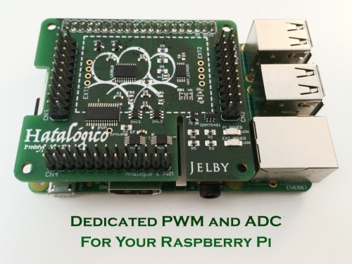
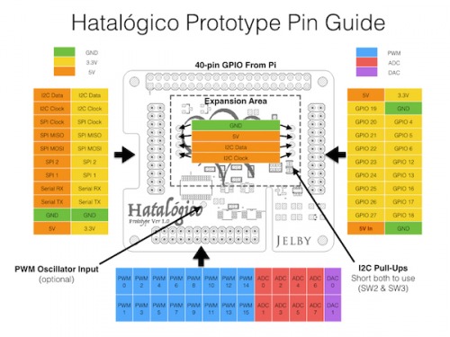
As you see Hatalógico is a powerful Raspberry Pi shield for most of usual robots. Here is the pinnout detailed:
This board makes Raspberry Pi much more powerful than most Linux/"Computer in a board" device without adding the hassle of another microcontroller and its extra programming. If you have any doubt, please check this following comparison chart:
Software
You can check the software to drive Hatalógico and general examples here: GitHub repo.
Also the code example for the weather station is here.
This is not just a copy of Arduino on Raspberry Pi: this is real power of Raspberry Pi directly to I/O hardware!
The main question: which Raspberry Pi works with Hatalógico?
- Any will work although only the B+, A+ and RPi2 fully support the 'Hat' specification.
- Any 26 pin model will still work although the DIO (digital IO) will have several unconnected pins.
This board is now at Kickstarter and we have the chance to help it to be real for everybody. It just need some right reviews in robotics applications, so we are the right guys, isn't it?
You know the deal: you get a free Hatalógico board in exchange you write an interesting review on your work containing: good explanations in English language, some pictures, schematics, all software and videos. The final idea is that anyone with a Raspberry Pi, the Hatalógico and external hardware (servos, DC motors, sensors...) can do the same project.
At his moment we have 2 Hatalógico boards to give away (maybe few more comming but not sure), so hurry up!
Here are the requirements of the two persons:
- Having got already a Raspberry Pi.
- Experience with Python.
- Have a robot project idea for Raspberry Pi and Hatalógico using PWM and ADC capabilities. Serial optional but interesting. Please describe the project in your proposal.
- Good social network connections (to share the review in her/his own channels too). Optional but interesting! Please provide links to your social networks.
- Member of LMR with at at least some useful posts with something I (or another LMR member) recognize as a useful post (to make sure that people not sign up only for this reason)
If you think you fit here, please comment below with project details and the Hatalógico father (John Lumley) will decide who will do the review and send the boards. ). He is reading this right now ;-)
Hurry up as this should be very fast!
If you have any question please don't hesitate to ask here, remember: John Lumley is reading here ;-)
FAQ
Why not use 3-pin connectors for easy servo/sensor connections?
There are a few reasons, some better than the others!
Space, to provide 16x 3-pin connectors on the space of a hat is difficult. To get thick traces for the supply and ground is nigh on impossible with the rest of the chips on the board. It would also need a separate power circuit also; the spec of which varies greatly depending on what you are building (the size of servos etc).
Standardisation. Or lack thereof. Most servos use the same pin-out for the 3-pin connectors. But not all, I bought two micro servos last week for the Weather Station project and they had different wiring.
Inflexible. Not everyone wants 3-pin connectors. What if you want 2 servos, 4 H-Bridge inputs and maybe an RGB LED? 3 pin connectors are only useful for some things and are a hindrance to others.
Why not provide motor controller, H-Bridge or <name another robot specific task here>?
Again, it comes down to flexibility. For how much current? How many motors? Encoders inputs too? Every robot is different and has different requirements on every front. Designing a board that is capable of driving your robot is impossible. I’m trying got provide a platform from which a knowledgable person can build what they want. This isn’t plug & play and it’s not really for absolute beginners. You will have to add circuitry to use this board in your application but I personally wouldn't want it any other way.
What kind of expansion is possible?
The sky is the limit due to the flexible footprint. You could make a board to sit on top of the Hat which pulls up whichever pins you want/need to use. There is a basic example of this in Part 4 of the Weather Station build (https://youtu.be/TbgEcstdr0s?t=12s). So if you want 16 servos on 3-pin connectors, you can make this on a simple perf-board in an hour or so. You only need to pull the 16 PWMs up through a dual-row connector and wire to whichever of the 3 pins is the PWM input for your servo! And importantly, you spec the power requirements to suit your needs.
Still breadboarding ideas? Just attach a ribbon cable. The PWM and analogue inputs use a 26 pin (2x13) connector so SparkFun’s Wedge and Adafruit’s Cobbler will both work to transfer the connections to a breadboard - using the (cheaper) 26 pin model obviously. I have designed similar boards for each of the three connectors which I intended to offer as a stretch goal on Kickstarter. I would invest more time and money on them if I thought that breadboarding was going to be a big use for the board. I don’t think that is the case but perhaps I’m wrong? Feedback on this issue is very welcome!
Design all finished? Perhaps you don’t need headers at all then. Solder directly to the through-hole pads and save a little head-room.
The board also features a small expansion area which I thought would be useful for little I2C boards which don’t require connections - 9DoF, RTC, GPS, Temperature/Humidity/Barometer, etc. (See the white-dotted lines in the photos, a board will fit inside these lines even if there is a ribbon connector on all three available sides).
Why this board instead of PropellerHat or Ardhat?
Firstly, I am a maker and I love boards like these too. I have used Arduinos in combination with a RPi many times and having an extra microprocessor is often useful. But that is not the point of this board. I wanted to create a board that expands the RPi’s IO capabilities and not just hand the tasks off to another uP. The original concept was for education. How can you teach kids about electronics without analogue inputs, DACs and PWM? However, my target audience has since shifted to robotics and general ‘maker' territory. One reason is that Arduinos are already common-place in schools and the Edison is getting big backers for their education push, I am not sure of RPi’s place in education despite their admirable mission-statement and achievements so far.
So, why this instead of the competitors? Because it’s 100% pure Pi and I love Raspberry Pi. It’s that simple really. It’s not just the Linux and GPIO combo that I love; you can get those from BBB, BananaPi, etc. But the RPi Foundation itself is a breath of fresh air with admirable ambitions and I want to help and support them.
Any other tricks?
The ADCs can be used a single-ended or you can use comparator or differential pairs. I’ve not experimented with this yet but Adafruit’s Python drivers for the ADS1015 covers this.
Level-shifted comms. The I2C, SPI and Serial are all available in 3.3V and 5V. Handy for connecting the Pi to 5V devices.
Power the Pi. The board complies with the ‘Hat’ specification’s recommended power handling to allow you to power the Pi from two pins on the Hatalogico.
If you have other questions please ask and we'll insert the asnwers here. Thanks!
https://www.youtube.com/watch?v=GcMWExBrB_k


