Build a 8A (4A per motor) dual motor driver for under $10

IMG_1084_resize.png

Need a 8A motor driver but don't have a lot of cash, look no further this article describes a simple and cheap solution.

This project uses just few electronic components, and can be build on a perforated board using hook-up wires.

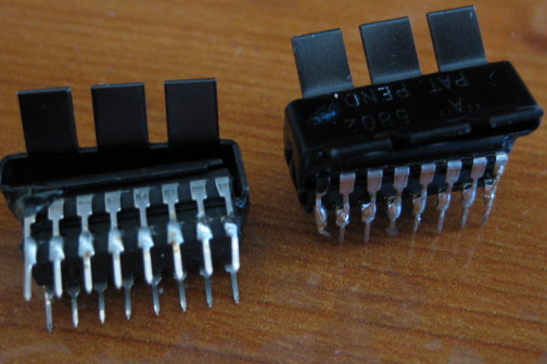
Texas Instrument's SN754410 is know to be a half-bridge driver suitable for low power applications it's rated current is 1A per channel. Costing only $1.55 it's a great choice for small robots on a budget.

Now what do you do if you need more power ? Multipy! Bruteforce ! Without much talk below is the schematic:

motor_driver_schematic.png

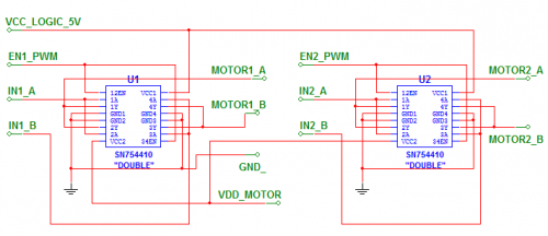
Sorry LMR scaled down the image, for higher resolution image see http://starlino.com/motor_driver.html

This schematic is easier to explain in words , than to follow. First note that "DOUBLE" near SN754410, this means that each chip is doubled by soldering another chip on top of it, I also added a heatsink.

Each SN754410 chip has 4 input channels: 1A..4A , and four corresponding output channels 1Y..4Y. We combine channels 1 & 2 and then 3 & 4. Thus each of our driver's input will use 4 channels (2 from each chip each capable of 1A).

As far as enable inputs we combine 12EN & 34EN for each chip. This is where we'll send our PWM signal.

If confused have a look at SN754410 Datasheet. I promise it's not that complicated ! According to page 2 of the datasheet SN754410 already has clamping diodes that should protect the chip from back EMF.

I built my driver on a peforated board using hook-up wires. With so many inputs and outputs it's easy to get confused so everything was labeled using my label maker. Have a look at the result:

IMG_1089.jpg


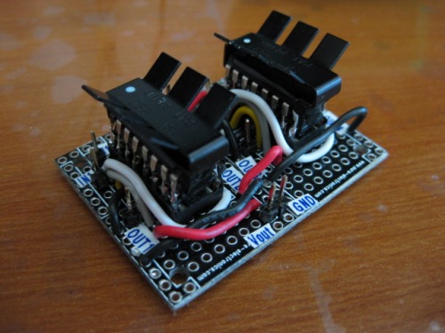
My tracked robot has 2 gearmotors with a stall current of about 3.7 amp. Octodriver handles up to 4A per motor. But I also used 2 resetable fuses with hold current of 2A , that would trip at 4A. Better safe than sorry :)

I'll try to keep you posted about the driver's performance with time. For more pics and updates check the main post of this project: http://starlino.com/motor_driver.html

Hope this was helpful !

Cheers,

//starlino//


https://www.youtube.com/watch?v=K3YbGWpU4UU

nice

I’ve read about stacking, but this is the first supersimple walkthrough I’ve seen.

I’m eager to hear more about your experience with it.
How hot does it get?
Does it’s responce characteristics change when it gets hot?

-I’ve heard that some chips will throughput more current when hot, while others throughput les. And to maintain a even ditribution between the parallelled circuits you need the later kind.

The theory being that if one circuit get hot it will take more current, thus getting hotter, thus taking more current, thus getting hotter untill it breaks. While with the other kind, if one chip gets hotter it will tighten up and force more current over to the colder chip, thus giving itself time to cool. Clever huh?

Interesting Idea
I have see transistors paralleled before in industrial stuff but never chips. My mini monster boe bot just uses some hi power hacked modified servo motors and works well so far. Not the speed a DC motor has but the torque for sure. I think at 6 lbs + for sure and can slip the treads. I do plan to switch to DC soon. Have a few of those motors laying around ready to go. You sure that is enough heat sink? Time will tell. lol

I’m using a driver similar

I’m using a driver similar to this setup on my balance bot. Quiet happy with it to be frankly.

Nice work demonstrating it. Will follow this subject :slight_smile:

Great idea!
I’ve have seen and built a design where I paired up outputs of a line driver to get more current, but stacking the whole chip and heat sinking it is really cool! I look forward to finding some big motors to test this with.

doesn’t that (outputting
doesn’t that (outputting less current when hot) apply to FET? In the schematic for that integrated circuit it shows as if BJTs, which act the opposite way afaik, are used.

mine never got hot, but it might depend on your application

I’ve been playing with this driver for several hours it never got “hot” just warm. But again it all depends how much current your bot consumes. I have a 4 pound tracked bot and here are the motor specs: http://www.lynxmotion.com/images/data/ghm13.pdf .

I added a video so you can see the driver in action.

My motors will never consume more than 4A , even when stalled. And I have a 2A (hold) 4A(trip) fuses on both motors “just in case” http://search.digikey.com/scripts/DkSearch/dksus.dll?vendor=0&keywords=srp200f

A resetable fuse will increase resistance quickly once the current reaches the trip current. It allows the motors and driver to cool off untill the “stall” situation is removed.

You should use the fuses if you know your motors would have a higher stall current than the driver can handle per motor (4A). For instance these motors http://www.pololu.com/catalog/product/1105 have a 5A stall current , and if you would be to use these - the resettable fuse is a must (Or stack a 3rd chip … ? :slight_smile: )

I had some reservation to this design in the begining. My paranoia was that one chip would switch sooner than the other and this might create a short circuit situation. In reality the chips are uniform enoght in characteristics. ( Although due to this paranoia I used chips from same production batch . I wanted them to be as uniform as possible.) For this same reason I would advise that you buy these chips in quantities of 4 if you want to build this driver.

Oh - and another advise, if you’re having heat problems: use thermal compound between you chip and heatsink this will help heat transfer.

Finally , best prices I found for this chips is at Jameco (1.55).


Great Work

Good job on your project

it’s nice to know that people out there are actually trying to find a cheap solution

to controll your motors.


I just had one quick question

can you stack 3 to get 6 amps per motor?

good job! I always had

good job! I always had curiosity to see this “hack” in action!! are you sure that this IC has the EMF protection diodes? because this subject has been discussed a lot in this forum and I think the conclusion is that the diodes are for ESD protection only. You can see a better explanation here. I know that a lot of people has been using this IC with absolutely any problem regarding power being kickbacked.

I would apreciate a lot if could you tell us a bit more about the fuses… what fuses are being used and how do you integrate them in your circuit?

fuses, diodes

I use resettable fuses connected in series with each motor (see http://en.wikipedia.org/wiki/Resettable_fuse ). A good guideline is your motor stall current, so if you’re mottor stall current is 4A choose a fuse with trip current of 4A. The “hold” current is usually half , meaning your fuse will start increasing resistance as it goes from 2A to 4A , and will trip at 4A. I find these types of fues a good protection against high currents, it protects my chips but also my motors (diodes will not protect your motors against stall situations). As far as kickback diodes you should probably also use them if you want to be on the safest side.


Is this limited to 4 amps or
Is this limited to 4 amps or can you stack 3 on top of eachother to get 6amps?

It would probably work with

It would probably work with 3 chips stacked , but look at the cost, instead of paying for 3 chips you can pick up a

TLE 5205-2 that gives you up to 5A and it’s about ~$6-7 each same as 3 x SN754410.

http://mouser.com/Search/Refine.aspx?Keyword=TLE+5205-2

http://www.infineon.com/dgdl/tle5205-2.pdf?folderId=db3a304412b407950112b4381da46a3c&fileId=db3a304412b407950112b4381e296a3d

sample product here:

https://sjvalley.com/shop/index.php?page=shop.product_details&flypage=flypage.tpl&product_id=13&category_id=2&option=com_virtuemart&Itemid=63&vmcchk=1&Itemid=63


Sweet! Thanks for the info

Sweet!

Thanks for the info

**cool, thanks for the info **
cool, thanks for the info :wink:

Relay
Or for five bucks you could just pick up a relay which can deliver 20 amps and go berserk :slight_smile: