Bottoo! Platform to test ranging sensors and algorithms

Update: 03/14/2014


I've finally mounted the awesome Open Source Laser Range Finder (OSLRF01) onto Bottwo with a panning servo to provide mapping functionality.


I was previously attempting to do this with the Sonar, but was stymied by limited range and cone size.


The narrow beam and greater sensing distance of the LIDAR will give me the ability to accurately map out a room in near real time, and then use the other sensors for closer proximity measurements.


How much is too much? 


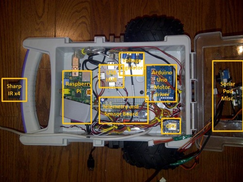
Yeah, I heard that!    Yes, I've got four  Sharp IR Sensors, two front and back for collision detection, two left and right for following walls at a specific distance.  

I've now got two more short range IR sensors  front and back facing the floor... so we don't fall down stairs again.


The purpose for keeping the front and rear panning MaxSonar is simply to fill the near field void that the LIDAR does not cover.  Because of the distance between the optics, the OSLRF cannot see closer than 1/2 a meter.  Also, like IR sensors, Laser is not fantastic at identifying thin objects like chair legs.  So I use the Sonar to sweep the near-field for collision avoidance as well.


I hope to have video up soon of this in action.


Update: 03/01/2014

I accidently left Bottwo "online" last night...  Usually, he is offline for charging or during my development, but there are small windows of time where other's have logged in to drive him around the house remotely.  Last night was apparently one of those nights...

Someone drove him to the edge of my basement stairs, and tested his "slinky" function.

Luckily, I had not yet mounted the Scanning Lidar on him, and the only things that broke were the camera/sonar pan/tilt, and the sealed gel battery ripped off it's cable...  (and a dent in the hardwood floor... don't tell my wife!)

Tonight, after repairs, I will be adding a front and rear Sharp IR GP2Y0D810Z0F floor sensor...   When my "Path Planning" algorith is completed, I should be able to disallow motion into such areas. 


UPDATE:  Videos added.

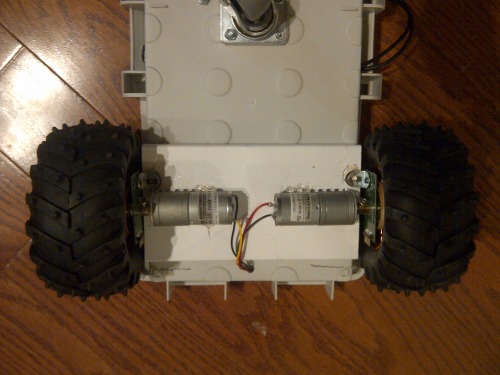
This is my second bot.  I just started it a couple days ago, and expect it will be a few more before I submit a video.  This one has low speed (50rpm)  high torque motors.  

My first one ran too fast for the wheel edge encoders, and if you drove him slow, he would stall under the weight.

Botoo (bot-2)  will be equipped with:

  • The I2C Sonar Pod that I'm working on.
  • A set of standard Sharp  2Y0A02 IR sensors on front/rear/left/right  ( I may also put two more on 45 degree front-right/front-left).
  • A pulsed line lazer with Webcam for Paralax ranging, and ....
  • I just bought a Kinect 

The purpose of this bot is to develop and refine routines for identifying landmarks (walls, doors, furniture) to allow for better interpretation of ranging data.


Update: 14/01/04

Got power supplies, Raspberry PI, and Arduino UNO up and running, and running simple sketches to tune wheel encoders.


Update: 14/01/07

So, this is the oldschool laserprinted encoder wheel and QRD1114 that I'm using on Robbie... I will admit to wasting more time on this little POS circuit than any other piece of this build.  

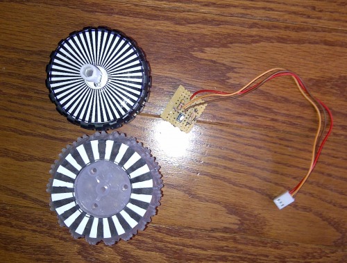
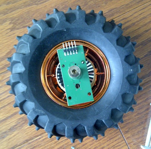
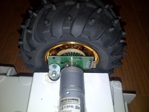
So, I treated myself to a commercial set of encoders from Solarbotics.  As well as the typical quadrature encode funtions, they have a CLK pin pwm modulated and a direction pin. (Also have a serial out with distance/velocity, but...) 

I had to enlarge the hole by a few thou to get it over the hub of my new wheels.  Not what Solarbotics intended, im sure... 

Fine print warned me against using it on anything other than their GM 2/3/8/9 gear motors...  My skull's too thick for that to register though...

And yes!!!  that is hot glue holding it all together.  Once I get the alignment validated.... then we'll put in the screws!

Update: 14/01/10

Telemetry control board - 1/2 completed...


Update: 14/01/16

Apologies for the slow progress on this.  Three kids under 7 means little time to myself or my projects.  :)

I'm all wired up now, and working on my code.  If I were to admit to having any skills whatsoever in coding, I'd have to say PHP is my comfort zone.  However I2C capabilities on the Raspberry Pi are pretty much non existent in PHP. 

I found this https://github.com/tbrianjones/raspberry-pi-i2c-bus/blob/master/peripherals/i2c_bus.php  as a good start.

I'm expanding upon this, using the Adafruit python I2C bus code as a template.

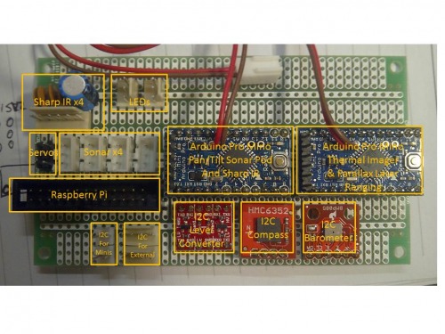
I need to read/manage:

  • HMC6352 compass module
  • ADXL345 3 axis accelerometer
  • BMP085 barometer and thermometer (also provides altitute via algorithm)
  • Arduino UNO motor driver / wheel encoders
  • Arduino Mini Sonar Pod and IR proximity 

I would love to hear from anyone who has had any experience in PHP on the Pi....

Update 2: 14/01/16

It's been a rather productive, yet expensive day.  I somehow shorted out and destroyed my 18v Lithium ION motor battery. Awesome! 

So, I'm improvising with 8 AA NiMH rated @2100 mah... we'll see how that does for now.

Here's is a picture of it's first "un-tethered" voyage....

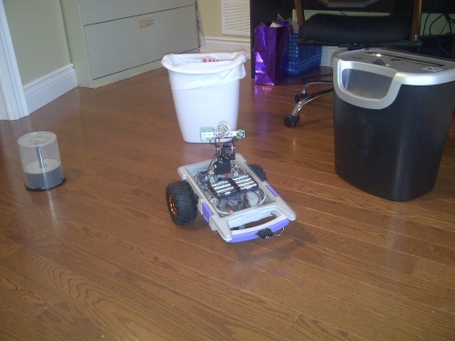
... and yes.... it hit the stack of DVDs.  apparently I was scanning right over top of them.

Video to come soon.  (Is this the part where I admit to my lack of skill at making/editing videos?)

Update: 14/01/26

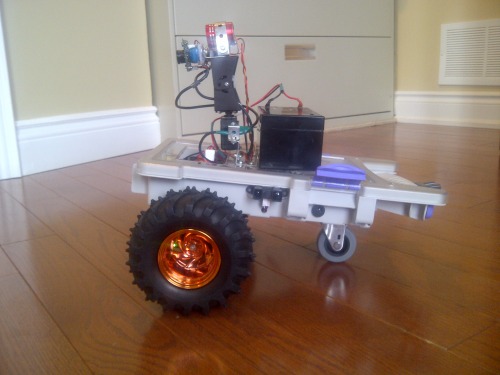
I've replaced the dead 18v Lithium Ion battery with a standard 12v gel cell.  Easier to charge, weighs a bit more, but... whatever...

I get bored easily, and have too many little things that I jump around between.  Lately I've been working on various routines for "self preservation".  Nothing extraordinary, just typical things like if the battery gets below a certain point, come back to base to charge .  The latest one was regarding wifi connectivity on the Raspberry Pi.   The routine would evaluate the wifi connection with the WebServer (commands coming in/telemetry going out) and if it hasn't connected in a while,  or the wifi signal is too low (small usb dongle inside chassis... bad idea...)  the rover would seek out a stronger signal.   Sounds great in theory.


So I went downstairs this morning, to find the rover huddled in my living room directly below the wifi router.... battery dead as a doornail.  Upon reading the logs, it appears that I accidently connected the routine that would send him back to the charging station on low battery with the new one that would attempt to correct wifi issues.    Battery got low, so he looked for a stronger signal!   Makes sense to me...


btw.... I said something like "Awwwww... it looks like he was trying to get a better signal..." in hearing distance of the wife...  She just looked at me, and said   "He?..."


Update: 14/01/27

Let's call this update "I'm no mechanical engineer!"

If you look at my pictures, this is a two wheel differential drive, with a trailing caster wheel.....  The caster is small, providing a slant to the chassis, which I kind of liked the look of, so didn't think to or bother to correct.

I've been wondering why turning has been "lurchy", as well as transitions from forward to reverse....

As it turns out, I should have just looked underneath during such "transition".   The offset caster, as it rotates, because it's pivot plane is on an angle, has to actually lift or drop the chassis.... including the rear-of-center mounted gel-cell battery....

Here is the "slope" of the chassis moving forward...

Here is the "slope" of the chassis moving in reverse....

I simply raise this issue to help others that may come across this.    Tonight, I will either be adding a spacer to lift the chassis, or preferrably installing a larger ball caster.


Update: 14/02/18

Just some new pictures... 

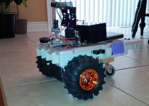
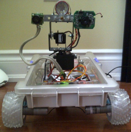
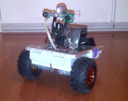
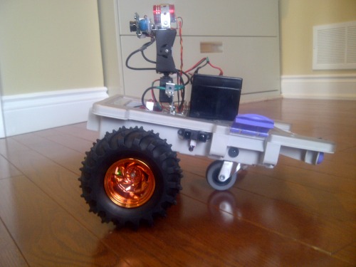
Profile (Ain't he cute?)

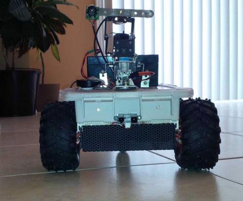
Head on... notice the Laser Line level and RaspBerry PiCam front and center for future ranging...


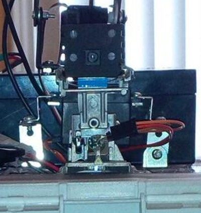
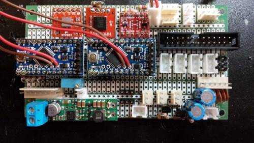
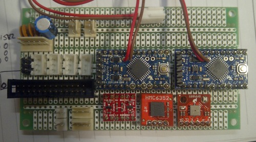
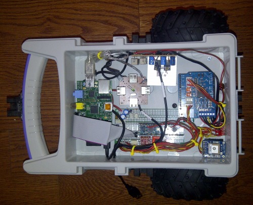
And this is the glue that ties the Pi to all of the sensory input....


Evaluates combinations of ranging sensors - Efficiently identifies and tags landmarks (yeah.. right...)

  • Actuators / output devices: two 50rpm 1:250 all metal gearmotors. 2 pan/tilt servos
  • Control method: semi-controlled. Raspberry PI runs Webpage for control
  • CPU: Raspberry Pi for main control, Arduino UNO for motor/encoders, and I2C sensors, Arduino FIO for Sharp IR and MaxSonar sensors
  • Operating system: Linux, Arduino
  • Power source: 18v 4000mah LiPo for motors, Dual 5v USB 8000mah LiPo packs for electronics.
  • Programming language: Arduino, Python, CLI php
  • Sensors / input devices: MS Kinect, wheel encoders, Sharp IR *6, MaxSonar *2 (on servopod), Parallax Line laser/webcam
  • Target environment: indoor for now...

This is a companion discussion topic for the original entry at https://community.robotshop.com/robots/show/bottoo-platform-to-test-ranging-sensors-and-algorithms

Wow, getting good! I love

Wow, getting good! I love that you’re using a Ras-Pi, if things are not going well with my Chumbi, that’s what I’ll use too. So I’ll have an example to follow. Cool!

It looks like a pretty cool

It looks like a pretty cool setup for your robot.  I am surprised you want to use two Arduinos but I am sure you have a plan where you need all the IO. 

I look forward to seeing what you come up with.  I like the Walmart parts organizer as the base.

Regards,

Bill


It’s more about timing and interrupts…

I found that a single arduino UNO (at least in my sloppy coding style) had a real hard time managing:

  • a serial stream of commands in,
  • serial feed of sensor data out,
  • run two DC motors via PWM,
  • monitor and increment two wheel encoders
  • run two Servos, also via PWM,
  • monitor two MAXSonar pulseIn 
  • monitor and translate I2C  info from Compass / Accelerometer

I’m sure I probably could have gone with a MEGA, or better yet move to a propeller chip, but I’m a big fan of modularization.  I figure I will dedicate one Arduino specifically to motor control with encoders and direct proximity IR, using Compass and Accelerometer for calibration/pose.  The Second Atmel will look after sonar scanning the environment and feeding it to the Raspberry Pi.


You PROBABLY could do one

You PROBABLY could do one Arduino with some careful programming.  But the extra IO could come in handy and the extra Arduino is cheap so why not? 

Good investment on the encoders.  I also spent a lot of time messing with a circuit and trying to get placement of the IR sensors just right. Never did get it to 100%; very frustrating.  I foresee a webcam attached to your RasPI and OpenCV in your future…  Thanks for sharing the pics of what you have done. 

Regards,

Bill


Thanks Proto. And so far under $50 for this board…

All in, connectors, proto board, 2 Arduino Minis, Compass, barometer… I’m not yet over $50.

When I go to fab, I’ll be using the Atmel chips, not prebuild Arduinos, as well as the compass, accellerometer, and a few other I2C chips…  I believe I can build this board for around $35 all in… In low quantities.


You’ll be in my first batch.

I owe you a debt of gratitute for some of the work you’ve published here.


Why do you leave diy

Why do you leave diy encoders, they doesn’t work correctly? The commercial encoders are really simple, but I don’t understand why they are so expensive. With that money it is possible to buy a raspberry (and more) that I think it is probably more complex.

Do you have some images that show better how do you connect the encoder to the wheel?

I’ve tried several DIY encoder circuits…

I’ve tried several DIY encoder circuits.  I’ve spent probably in excess of 200 hours just on this problem… Not a waste, really, I’ve learned alot.  Will probably go back to them at some point.  But it was distracting me from the objective of this build.  And frustrating me as well.

These Solarbotics have an ATtiny chip onboard that cleans/processes and decodes the pulses.   ok… ok…  I got lazy… LOL 

They just work.  position them 1.6mm from the reflective disk, and you get 128 pulses per revolution, with direction.   My DIY version would drop out from time to time, or saturate if the wheel speed was too great, or REALLY saturate if you were driving into the morning sun across the kitchen floor…

I’m not done with DIY… I’m just done on THIS bot…


Re: Do you have some images that show better how do you…

Do you have some images that show better how do you connect the encoder to the wheel?

I’m not sure I understand this question.  Mechanically connect to the wheel/chassis?  Or electrically, as in wiring?

I had to enlarge the shaft hole in the encoder board a bit to allow for my hub to spin freely.  After I afixed the relective

encoder disk, I slid the encoder board over the shaft, and held it in place 1.6mm (roughly) from the disk with kids modeling putty.

I slid the shaft of the wheel onto the motor shaft, tightened the nut, and hotglued the encoder board to my chassis with an “L” bracket.  When it set, I removed the putty.


Clarington-20140126-00516.jpg

Clarington-20140126-00517.jpg

This is what the encoder board itself looks like...

gmww02_-_img_6974.jpg

Does this help at all?


Yes, I mean mechanical. No

Yes, I mean mechanical. No other questions :P, good work.

The answer is more than complete.

Thank you unix_guru


can you showing and talking

can you showing and talking more about your not yet installed LIDAR ?

I’ve got a Blog entry on it…

Pictures of the build… https://www.robotshop.com/letsmakerobots/node/40573

The LIDAR optics arriving… https://www.robotshop.com/letsmakerobots/node/40537

Link to the OSLRF-01   https://www.robotshop.com/letsmakerobots/node/40441


Much more to come…


LIDAR Lite can measure down

LIDAR Lite can measure down to zero… Just sayin’. :) 

I really like this bot because I have a thing for sensors.  Are you planning some comparative testing of the sensors or just seeing how many you can fit on one bot? Didn’t see any trusty SR04s on there…  Not good enough for ya? 

thx a lot, I collect all !

thx a lot, I collect all !

I’m ultimately looking for a fusion of sensors

The LIDAR is good for mapping and rangefinding, but not great at detecting small obstacles locally (even the really expensive ones) bu the Sonar, with a much wider cone can tell you something is “somewhere in this area at this distance”  which is good for collision avoidance. 

I’d like to ultimately have a data feed that combines the two data types. In-field wide angle, and  Outfield narrow angle.

I has the SR04s initially on my first bot https://www.robotshop.com/letsmakerobots/node/39052   but soon traded them out for the MaxSonar.  Was hoping the the narrower cone of the MaxSonar would help me with Rangefinding, but it became apparent that I could reduce my pan increment to 5 degrees and still see no noticeable difference in the output… so…

After I do some more work on the Mapping and Localization piece, then I’m going to look at comparing the various sensors systematically. 

And yes… LOL… Will be picking up a LIDAR Lite to add to the arsenal.    I’ve also got a Kinect sitting on the shelf waiting.  The problem with it is, it is bigger than by bot! 


Awesome! It would be very

Awesome!  It would be very interesting to mount the different sensors on the same pan bracket, sweep the area on front of the bot, overlaying the results on to a single display or downloading and plotting them on a pc.   Would be a great start to a wiki article… 

I had thought about getting a bracket printed up…

I had thought about getting a bracket printed up that would hole the OSLRF, a Sharp IR, and a Sonar al in the same plane.  Should be “fairly” easy…


Another Laser Sensor Possibility?

There might be another possibility for a good obstacle detection/mapping sensor that would be quick and not need to pan to get detailed data.  I haven’t tried it but I think it would be doable.

1)  Put a $10 laser (that shoots a line pattern or a cross pattern) low on the bot shooting out horizontally forward and level to the horizon.  Maybe an inch or two off the ground.  This line will spread out to give you 30-45 degrees of coverage at the same time.  

2)  The laser line will take various shapes depending on what it hits and at what angle.  Example, if it approaches a wall hear on, a level line will be produced on the wall.  If it approaches at an angle, a line sloping up on one side will result.  If a narrow obstacle is in the path, a short line will be seen on the obstacle, with the rest of the line disjointed on whatever is behind the obstacle.

2)  Use a camera mounted higher up in the bot and open CV to look at the line and filter for the intense red/pink of the laser.  I have tried this and it works.

3)  Evaluate the shape / slope / number of segments / position of the line to estimate.  (haven’t tried but it seems like basic geometry and a little stats)

1.  Distance

2.  Obstacles

3.  Angle of Attack (when near walls)

4)  The strengths would be being able to evaluate an entire wide field of view in a single frame, with great granular detail, without panning.  The weakness is this would not cover the vertical dimension.  Perhaps two or three lasers could be used to cover various heights, but this would start beaming people in the eyes.

Looks like you might have all the pieces on your bot and skills to take a whack.  Hope there is not some flaw in my thinking, I tried firing a laser and looking at the patterns quite a bit.  It seems doable.

Martin

It’s already on there…

If you look at the picture below, you will notice the Raspberry Pi cam (5megapixel?),  and about 6cm below you will see three wires feeding the Laser (power / ground / pulse.  A cm  below that, you will see the slot for the laser exit.  This is a dismantled Black and Decker Laser line level.

laser_line_level.jpeg


It works quite well, and definately requires more attention, however unless you dedicate a processor akin to the Raspberry Pi to this function, you end up with a "run-stop-look-run-stop-look" method of travel. 

My goal is to take measurements while traveling.  Even with my panning sensors, I send a time stamp and a frame stamp with the distance samples that can them be aligned with wheel encoder position to get point in time measurements while traveling.  The arduino can handle this data mapping readily.

I frequently get told I've got too many processors onboard... nope... I'm good with it.