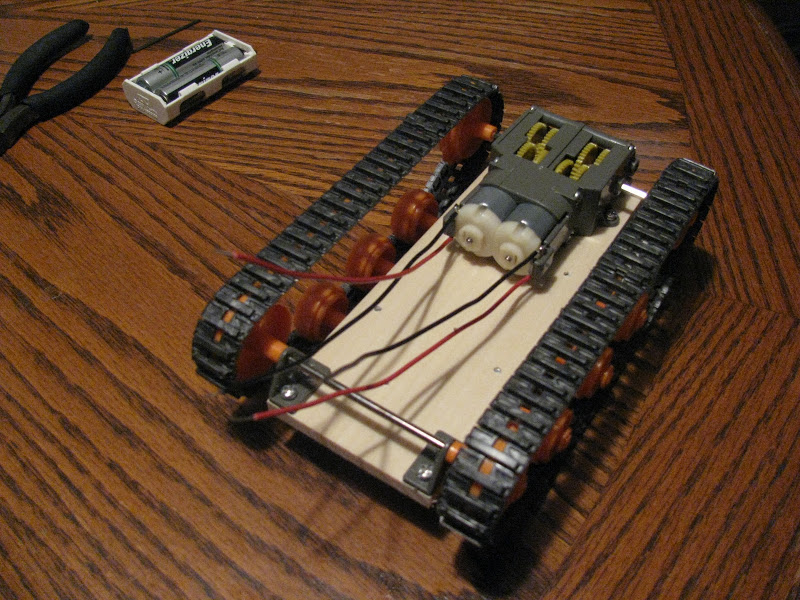
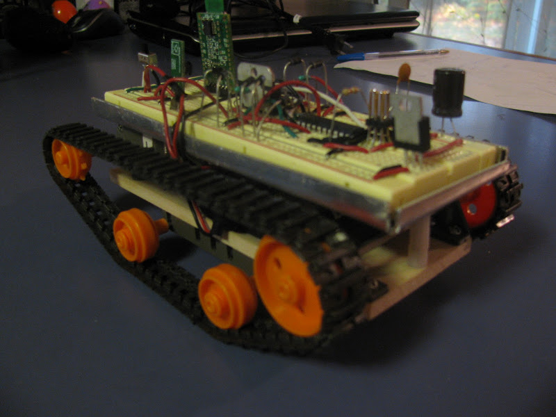
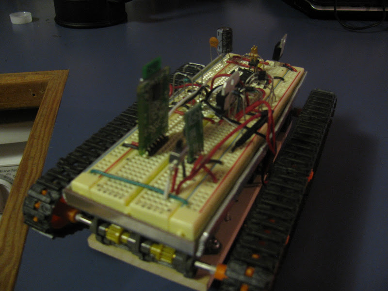
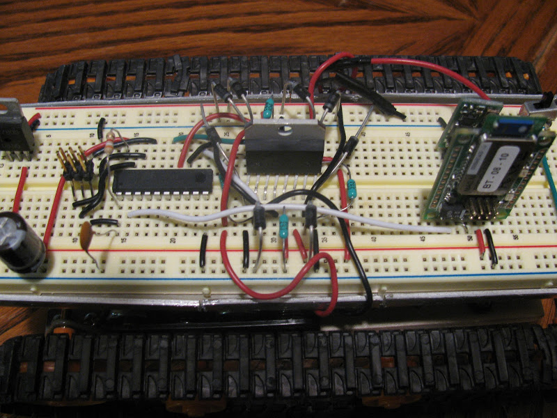
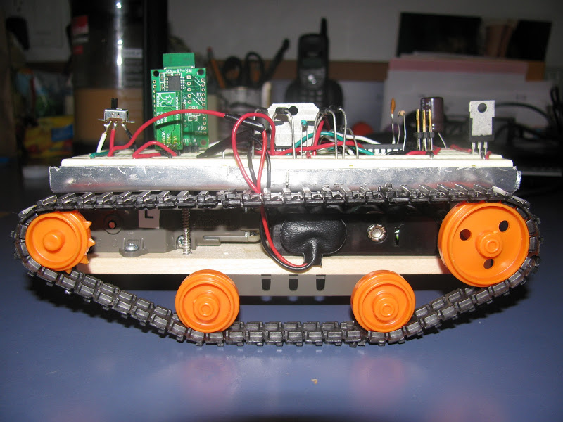
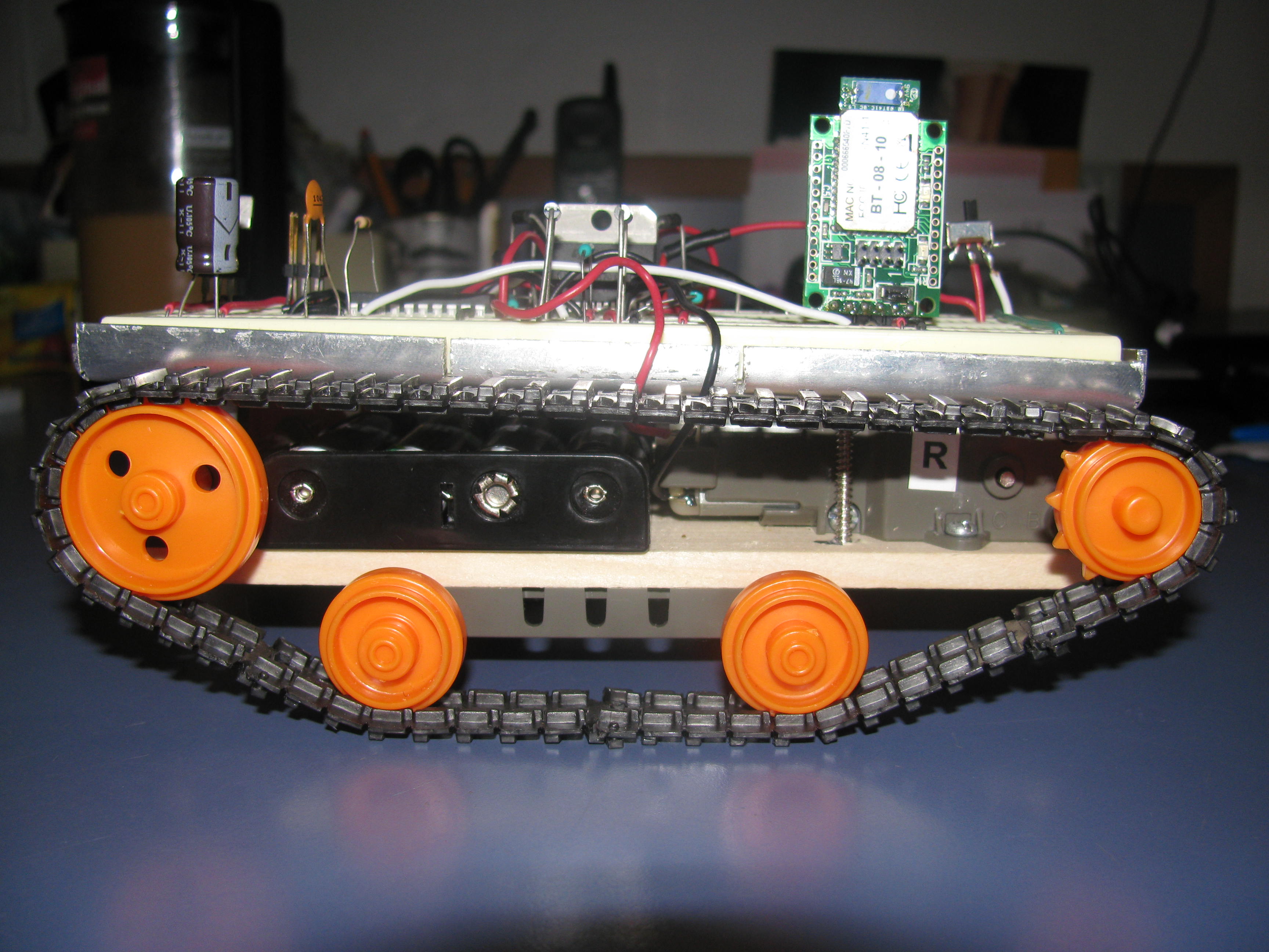
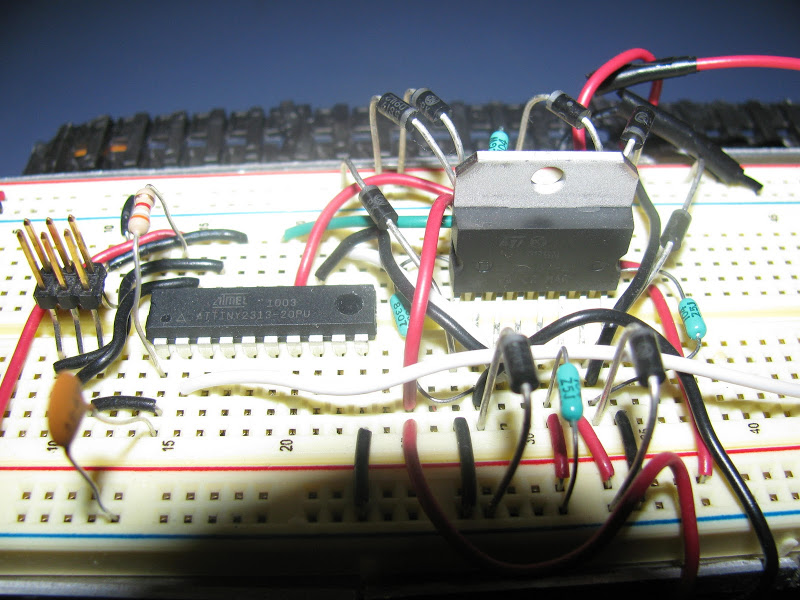
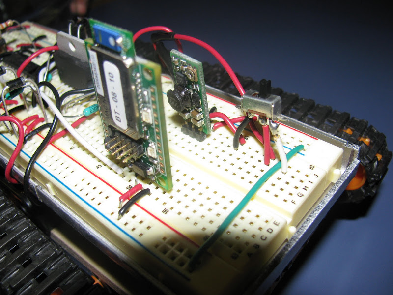
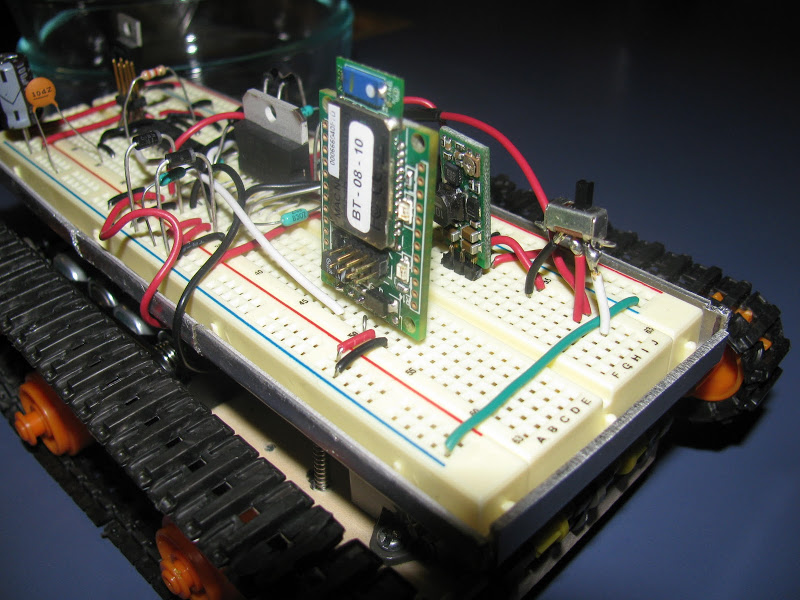
This is my first robot using an Atmel ATtiny2313 Microcontroller. It uses an L298N H-bridge with no PWM, with plans to add PWM. I've included schematic and code in the files. The high current/low voltage Tamiya motors were swapped out for Solarbotics RM3 motors. The gearbox is a Tamiya Twin motor gearbox. The Bluetooth module is the Roving Networks RN-41-SM and is available at Mouser.com for $45.
The Cell phone is programmed in Python for S60 v2.0.0. The computer program is a LabVIEW 8.20 virtual instrument control. Remove the _.txt extension when using these two files.
UPDATE:
I've added PWM for independent speed control of each motor as a function of accelerometer values in the phone. The last video shows a demonstration of the PWM version. The zip file 'Bluetooth_and_accelerometer_RC_tank_with_PWM.zip' includes all PWM version code and updated schematic. This revision was mostly changing code - the only hardware changes was the addition of a couple of wires to connect the PWM outputs of the microcontroller to the enable inputs of the H-bridge, which required moving a couple of IO pins to get at the necessary dedicated PWM pins.
The improvements made to this revision:
PWM
Graphical accelerometer feedback on phone python script
Bluetooth automatically turned on when off in python script (before it failed when BT was off)
New communication scheme to transmit direction and PWM commands to vehicle - has the form {<dir><left PWM><right PWM>}
Automatic shutoff - microcontroller firmware stops the motors if no commands are received within 100ms (accomplished with 16-bit timer), which prevents the robot from continuing to move when the Bluetooth connection is terminated or fails. This requires the phone to transmit constantly.
You may also notice it looks more responsive. That's because I was using a lowpass filter when reading accelerometer data in the first revision, oops!
Controlled via phone accelerometers and Bluetooth
Actuators / output devices: Tamiya gears and tracks
You got a lot going on, on that solderless board. I also noticed you have a adjustable boost regulator. Is that for powering the motors, or just getting more life out of the batteries? Controlling this robot by BT with your mobile phone is rather awesome. I am looking at getting a BT module, but the bluesmurf is around 70$ AUD so, I might checkout the gps module instead.
There are cheaper alternatives to the Bluesmirf gold from SFE
Thanks Rich, I started off with a solderless board since it was an evolving circuit and first bot. The adjustable boost regulator does power the motors, which I spec’d to be lowish current at about 7 volts. I wanted to minimize battery size and weight, so that’s why I used it. The other reason is it was hard to mount a six-battery holder since it has no mounting holes
Anyhow, after having my first Bluetooth module, a Bluesmirf from sparkfun, die after a few months I was not going to drop another $65 on another. I found Roving Networks sells a breakout module better (IMO) than the bluesmirf for $45, the rn-41-sm. I recommend this module as it is easy to use, enables two different through hole configurations, configurable via Bluetooth link, has a good AT command set, and has an RS232 smd IC as well (requires removing two tiny smd resistors for use without RS232 IC).
You might try soldering an RN-42 Bluetooth module (class 2, range of 10+ meters, $20 USD) upside down and using small gauge wire for the few needed pins, and only worrying about soldering one or two of the ground pins. Perhaps I will try this and create a tip for cheap DIY Bluetooth. It might not be meant for the average bear as it is very fine pitch.
I am thinking for my next robot I will make something a little bigger, faster, and add vision using a wifi webcam which will be processed on a nearby wireless computer to send commands back via Bluetooth, and have a microcontroller receive the commands to control motors for various functions. I will be studing OpenCV in the mean time for proof of concept.
I forgot to mention another great point about voltage boosters, The output stays a constant voltage even as the battery charge and voltage decrease. This results in the robot having a consistent speed throughout the life of the battery charge. I got the idea from Pololu’s 3pi robot.
It can work with an iphone but you will need to develop an iphone app for it. I haven’t personally develped on the iphone so I can’t tell you how easy or difficult it would be. All I know is it can be a pretty steep learning curve. Two hardest parts of the application will likely be accessing the phone accelerometer data and setting up bluetooth communication. I am sure it can be done on an iphone though.
I don’t have a Mac either, I prefer to build my own hardware as you can probably tell from the video showing my quad monitor setup. I bought the Nokia phone specifically because I can program it with Python, as well as C and Java. Python is awsome for Bluetooth applications and in general.
I love the phone integration. Hey, just wondering, did you have the same problem I did with the rubber tracks coming off when you drive on a slightly sticky surface, like a synthetic carpet?
Ohhh yeah, these tracks are a pain and come off on carpet when turning… but much cheaper than anything else. I even left them in my hot car once and the tracks lost their elasticity so I had to replace them! (the tracks can be bought seperately) Learn from my mistake
Great setup my friend. Works great with the cell and bluetooth. I wish I could do it with my iPhone 4,unless it would have been jailbreak, your cell works on Android I presumed. Thanks for the explanation
So far I have only programmed a Nokia phone running Symbian operating system. I will eventually port the cell phone code to Android operating system as Python is available on that platform as well.
Hi, this is great, I specially liked what you did with your phone’s accelerometer.
I have the same bluetooth module and my question is how robust is this module, I mean do I really have to worry about static discharges and also what precautions do I have to take while I solder wires to the pins?
When I’ve soldered the bare module (RN-41) I used a grounding strap, although I don’t think I was in a static prone area (I’ve previously made a breakout board for the RN-42). I also followed the soldering temperatures specified in the datasheet, which requires a temperature controlled soldering iron- I had to leave the iron on the pin for about 30 seconds for it to warm up, and longer on the grounds. If you are using the RN-41-SM which is already broken out then I’m sure you can use higher soldering temperatures with it at the breakout pins. The module is probably pretty robust to harsh treatment but I’m more paranoiod than most people