

*** Hot Breaking NEWS ***
I'm reopening this case file. While revisiting the PIC firmware for this, I found a stonking flaw in my servo output timing. My pulses were happening every 48ms. They shouldn't be more than about 1800ms apart. I don't know why I didn't spot this on a scope months ago. This MAY account for the servo jitters mentioned later, but more importantly, my patched software now drives my MG995 servos! This means I now have enough mechanical power to swing the upper torso weight (battery) from side to side!
Watch this space.
Bipedal Walking Robot Concept
Why?
There are many walking robots, including bipeds, available from several vendors. They are mostly highly priced: something like the brilliant RoboNova would easily set us back US$1,000. If we aim our sights at a less expensive, less functional piece, it still might run to UK£200. My objective is to create one for under £50, from parts available at any DIY shop (including eBay!) and reusing as much of the stuff I already have lying around.
Materials
Having tried several materials, such as right-angle aluminum extrusion, I found none of them suitable and was on the verge of giving up. To have the pieces fabricated would defeat the purpose of the exercise and was going to prove massively expensive. Late in November of 2007, I settled on a most unexpected material: box section PVC plastic ducting.
This stuff is typically used in home extraction fan systems and is sold at most DIY shops in 1m lengths for around £8. If I hadn't botched so many of my first attempts, I'd say that a 1m length would have been plenty to build a functional pair of legs and a body core.
The choice for motorising the legs was not so difficult. It had to be the servos used in radio control toys. These can be positioned quite precisely, have a rotation of about 180 degrees and can be controlled directly from a microprocessor with no worries about position feedback. As it happened I had many of these around as I am a fan of R/C cars. If they're sought new, they can be obtained readily on eBay. At the time of writing, £12 would readily buy you FOUR!
Having been reasonably satisfied with M4 bolts for holding things together (complete overkill for a plastic toy, but readily obtainable and inexpensive) I found these lovely little 4mm plastic rivets on eBay. They hold things together amazingly well.
I've been programming Microchip PICs for a couple of years in their native RISC assembly language and am quite comfortable with that, so the only debate over the choice of control hardware was: which one should I use? (More on that later.)
How?
After prancing around the house for several days, trying to bend only one joint at a time to establish which ones I really needed in order to walk, I concluded as follows. I need:
- ankles which bend up and down (pitch)
- knees which bend back and forth (pitch)
- and hips which bend forward and back and which can rotate (pitch and roll).
Of course this is only one minimum set of required joints. Other minimum sets of required joints to facilitate walking are available. I'm certain many PhDs have been written offering many more options. Also, feel free to correct me, but my understanding is that this equates to four "degrees of freedom" (DOF).
Oh. One more thing comes to mind: when lifting one leg, it's likely to fall over. That's OKay, because when we walk, that's basically what happens. It's a kind of controlled falling. So, how do we control the fall a bit better? We have a heavy torso, which can be twisted and shifted. The best solution I can come up with is to mount the weighty component of this robot (the battery) pretty high up on a beam parallel with the "waist." This beam will be cross-braced (triangulation style) by another servo. Thus, the servo will be able to shift a large weight from side to side to counterbalance.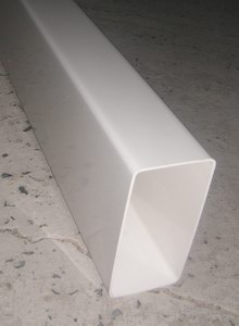
Construction
The Leg Parts
As documented elsewhere, the main material is 56mm flat PVC ducting. This was run up a bandsaw twice to create two lengths of 54mm x 17mm U-section.
Annoyingly, when the duct was cut lengthways, the top edges of the section bent in towards one another. This is probably an effect of the way they are cooled in the factory. In order to make the opposite faces parallel, they were wedged apart with an appropriately sized piece of timber and a blowlamp applied to soften them.
Every effort was made at the design stage (yes, there WAS a design stage) to make the components as similar and generic as possible. Each leg has two identical "leg pieces" (what an inventive name). They are short lengths of the U-section with cutouts at each end and the ends rounded so that they can rotate inside one another. There are holes drilled at the centre of the round edge and more holes for mounting the servos.
The servos are held in place by two means: there is a protrusion in the top which fits quite neatly into a 12mm hole and which takes most of the sideways force. The servos are prevented from rotating by four of the 4mm plastic rivets mentioned elsewhere.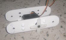
The leg pieces have the drill pattern applied to both sides so that the servo can be mounted in either side (or if the design is rotated, the servo can be mounted "upside-down").
Hip Joints (Pelvis)
Affording a second degree of freedom, these were more awkward than the ankle and knee joints. This time, the servos were mounted facing downwards from the "pelvis" of the robot. Holes are bored in the "top" of the hip joint and the servo head protrudes. The horn is mounted on the underside of the hip joint, to which it is secured with several small screws.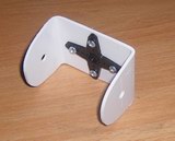
Without this added degree of freedom, the robot would only be able to walk in a straight line. It is hoped that hip rotation will allow it to change direction. Here we see the "hips" from the underside. Only one leg is attached (the far one) and on the near side, we can see the servo head protruding.
Balancing Act
The robot will carry a power source (a 7.2V racing pack of the Tamiya type commonly found in radio-controlled cars). The square frame ("torso") visible at the top of the topmost photo is hinged at every corner (in the same manner as the knee joints). There is a servo mounted on one of the joints, which is capable of deforming the square into aparallelogram. The battery is mounted on top of the topmost beam. With this mechanism, the weight of the batery can be shifted from side to side and it is hoped that this will allow the robot to balance while one foot is off the ground.
Control Electronics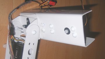
The interface between the control computer and the servo motors is reasonably uncomplicated from an electronics point of view. A TTL/RS-232 line level converter (MAX-232) acts as the interface between the control computer and a Microchip PIC microcontroller. This microcontroller creates 10 unique square wave outputs. I'm not going to bore you with another description of those outputs unless the thousands of websites which already do such a good job all die. Examples are:
- Society of Robots
- Seattle Robotics Society
- Digital Nemesis
- Bob Blick
- Instructables
- etc.
One note, though: many sites refer to this as "Pulse Width Modulation" and, I suppose this is correct as we are modulating the width of the pulse. That said, don't fall into the trap I fell into when starting out. The "value" of a PWM signal is often derived from the mark to space ratio. Don't assume that the servo position is a function of the mark to space ratio. It isn't. The servo position is derived purely from the width of the "high" pulse. At the same time, the entire duty cycle does need to be between 5 and 25ms.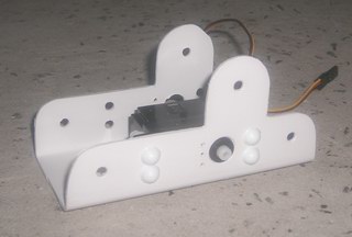
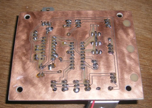
I noticed that standard Radio Control servos can easily draw 300mA at stall and a bit more when starting to move. This was causing my PIC to reset and my solution was to split the incoming battery power four ways through four 5V regulators. One regulator supplies the PIC and the serial interface and each of the other three supplies power to two or three of the servos.
That aside, my circuit has an LED. I like flashing lights.
By the way, I made this PCB myself. I'll need to create a separate blog to show you how. Sure, it's been done before, too, but I really like my process. This is my first attempt at printing the component side.
Communications Protocol
(Watch this space. It's likely that this protocol, or a superset will be used in the modular robot electronics project.)
In order to allow communications between the robot and a control computer (a PC in the first instance and a Palm Pilot in the final piece), a protocol was devised.
Early on, it became apparent that it would be limiting and require a lot of unnecessary work to devise a system which would only allow specific commands to be sent to specific parts od a specific PIC project. The decision was made to devise a protocol which would allow any RAM address in the PIC to be modified via its USART port. IMP (Inspection and Modification Protocol) was born. As a side effect, it can also be used to inspect and modify the SFRs and plans are afoot to investigate mechanisms to directly address any EEPROM which maybe available.
To start a "conversation", the control computer might send any (or all) of the following commands to the PIC:
- set bank
- set address
- set bit index
- set value (low byte)
- set value (high byte)
 The commands cause some internal registers to be set in the PIC which hold the bank, address and value, etc. of the bit or byte (or word!) about to be inspected or modified. One these registers are set, they remain set, so if all of the RAM to be accessed is known to be in bank 0, the PIC only needs to be told "set bank 0" once. Likewise, if only one RAM location ever needs modified, it only nees to be told "set address nn" once.
It then follows with one of:
- modify bit
- inspect bit
- modify byte
- inspect byte
- modify word
- inspect word
which causes the information given in the first phase to be used to inspect or modify a location.
Of course, the textual names of the commands given are not actually sent on the serial port: each of the above has a corresponding byte, so each command is actually only one byte in size. NB each item in the first list above also requires a data byte to be sent.
Rather than the user supplying the address of the data to be modified, the client holds a copy of the symbol table, so it is able to look up any given symbol to establish its address.
By way of verification, each command byte sent to the PIC is echoed after it has been executed. this means the PIC does not require a software receive buffer, but that the host is responsible for ensuring that no data byte is sent until the echo from the previous has been received.
Software (PIC)
The embedded software was written in Microchip's native RISC assembly. I'm perfectly comfortable in that environment.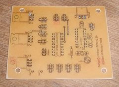 Software (Palm)
Although it was never mounted, I have written the client program in yBASIC on my Palm Pilot Vx. It works really well. The Palm is an amazing robot control device. Join me in campaigning for the introduction of serial port code to iziBASIC.
Software (Windows)
The client used for most of the debugging was written in National Instruments LabVIEW 7.1. It's the ideal control programming language with readily available user interface components, and it's graphical, so it's an option for non-programmers. Unfortunately, a $1,200 pricetag means unless you're using it at work, it's not really an option for homers. (If you're a professor, you can get it for free!)
Not a lot of people know this (and probably fewer care) but LabVIEW is the backbone of the Lego Mindstorms RIS for their RCX product. As I understand it, RIS is basically a cut-down version of LabVIEW.
Summing Up
Mechanics
The design was acceptable. The construction was rapid and the result showed the haste. The pushrods were a mistake. They introduced far too much slack into the system, particularly when the joints were at their most straight. Consequently, movement required to be slow in order to avoid overshooting a slop-point.
Having raved about how great the little plastic rivets were, they turned out not to be so good. The interference-fit rings which held the rivets in place seemed to split reasonably often and in many cases I reverted back to M4 bolts with nylock nuts.
Software
The PIC software was allright. It was always jerky: the bot sometimes looked like it was shivering. I suspect this is because so many clock cycles were used in the main loop that the length of the high part of the output pulse was in a state of flux. I can't see a way of demonstrating this without a digital storage scope. The communications protocol was spectacularly robust.
Electronics
With analog electronics not my forte, I often wondered if my power distribution (a handful of 1A regulators powered in parallel, each distributing power to a group of the servos) mechanism was the best approach. I couldn't think of an alternative. It didn't overheat, which may be more of a comment on the large chunk of aluminium I hung off it. That aside, I definitely selected the correct microcontroller for the job and the TTL/RS-232 interface is an amazing little chip. I should have included In-Circuit Serial Programming (ICSP).
Future Work
I need to think a little more about the mechanical side of things to reduce the amount of slop in the joints. I need a more powerful motor or a completely different mechanism to shift the balancing weight around.
In summary, for a first project a biped was probably over ambitious. Maybe I should cut my teeth on a hexapod next!
For now, it does squats. Hopefully, it will eventually walk in a controlled manner.
- Actuators / output devices: Acoms AS-16 Servos
- Control method: RS-232 Serial
- CPU: Microchip PIC 16F628
- Operating system: IMP (Custom Protocol)
- Power source: 7.2V Tamiya-style racing pack
- Programming language: Mixture of PIC RISC, yBASIC and LabVIEW
- Sensors / input devices: none
This is a companion discussion topic for the original entry at https://community.robotshop.com/robots/show/biped-walking-robot-from-a-piece-of-pvc-conduit


