Big Motor Driver Done

***Update***

Well, it seems I might have smoked something. I am in the process of testing the motor driver, with a load, and using 2 motors. While my "B" channel seems to be working fine, the "A" channel seems to be stuck on. Not to mention, the FET driver sorta burned my finger when it was touched. All this and I have yet to blow my 20 AMP safety fuse! I'm letting it cool off a little and am going to try again. ---I am not looking forward to asking for "purchase authorization" from the wife for more parts!


What started as a simple question about running big motors has turned into 2 threads and over 110 posts.

First Post

Follow-up Post

What has come of this is wonderful submissions from BOA, GroG, Robologist, Krumlink with Rik and others filling in a bunch of gaps and disputing what everyone else has said. I have gleaned what I could from this firehose of posts and decided to go with the BaseOverApex/ Robologist plan. As an overview this is a high power motor driver with logic level inputs for PWM and "reverse", a FET driver chip and FET's for main power switching and 2 high power relays for reverse. Here is the original schematic from the second follow-up post "H Bridge Matrix":

BOA's Brilliant Hybrid H Bridge - Robologist Mod

BOA's Brilliant Hybrid H Bridge - Robologist Mod
Description BaseOverApex's design of a great Hybrid H-bridge. The hybrid is a combination of relays and MOSFETs. The relays are for forward and reverse switching. The MOSFETS can accept a high frequency PWM for speed control. This design has been built (not just theory) and is currently powering one of BOA's great bots. Hopefully he will post a version of the PCB art - although it might be good to rework it so that the PIC is not part of the design, as others might be using different methods of control.
Original Author BaseOverApex robologist
Built By
Max Current 15 Amps - limit by relay
Max Voltage 12 Volts to 15 Volts
Build Time 3 Days?
Pros strong, low cost
Cons not quicklyswitchable forward to reverse, limit by relay
Max PWM Frequency
Features reverse flyback diodes, MOSFET driver
Parts List
Desig  Qty  Part#           Each  Total    Dist      Description
*K1,K2 2 PB897-ND $4.44 $8.88 Digikey Tyco PCLH-202D1SP,000 12VDC/75 mA coil, 15A relay
*Q1,Q2 2 IRFZ44NPBF-ND $1.89 $3.78 Digikey IRF IRFZ44NPBF 49A 55v N-chan FET TO-220
*Q3,Q4 2 P2N2222AGOS-ND 0.36 0.72 Digikey On Semi P2N2222AG 600mA 40v NPN GP BJT TO-92
*D1-D8 8 497-2753-5-ND $1.09 $8.72 Digikey STMicro STPS1545D 15A 45v Schottky rectifier diode
*U1 1 TC4427CPA-ND $1.05 $1.05 Digikey Microchip TC4427CPA 1.5A MOSFET driver
*C1 1 4035PHCT-ND 0.81 0.81 Digikey Vishay 220 uF 35 v Electrolytic Cap
* Total $23.96
Schematic
BreadBoard Image:M relayhp B.jpg
Gerber Image:M relayhp gerber.jpg


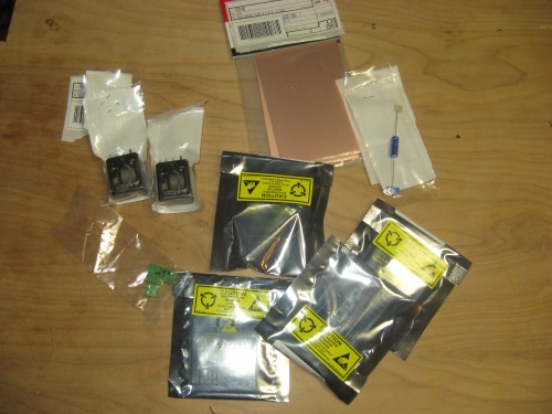
I bought all the parts on the list above, all from Digikey, with the addition of some blank 2oz copper PCB boards and were quite happy when my parts arrived within 3 days!

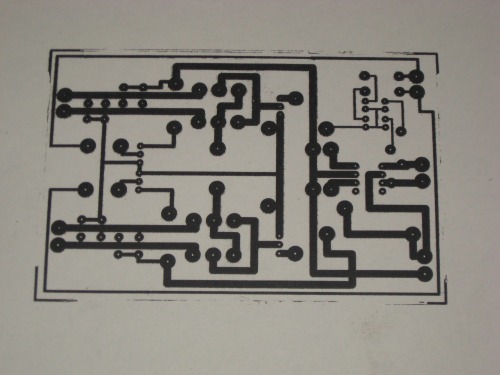
Next, using PCB123 layout software (which is not only free, but worked quite well) transposed the schematic into a PCB layout. In general, I was able to keep most + runs to the outside and - to the inside. I think I did pretty well, only needing 6 topside jumpers. I must admit, it was a nightmare to keep all the componant's polarity straight as I went as things are mirrored or double mirrored (depending how you think about it) in terms of the top side of the board, bottom side and the fact the transfer is reversed when applied to the board. The picture below is of the final transfer I used.

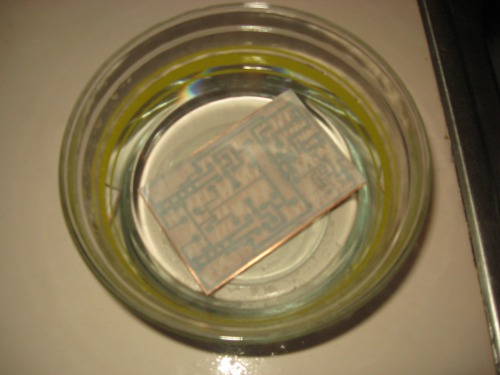
This layout, printed with a printer using ink, was taken to my local copy-shop and Zeroxed as dark as it would go using a standard copier using toner. Next, I ironed the ■■■■■■■■■■■■■■■■■■■■■■■ of the transfer onto my blank PCB board. I was careful to go over each line one-by-one in addition to placing the iron over the whole transfer and putting my whole weight on it.

That would be:

140 Lbs

63.5 Kg

10 Stone

Happy that indeed the ■■■■ had been ironed out of it, I soaked-the-crap-out-of-it and then rubbed off the paper.


With a little scotch-brite (green scratchy pad (for dishes)) I removed the toner from the circuit lines, drilled and soldered away. The tiny little drill bit came from a model airplane shop, chucked-up in a dremel tool and was done by hand. Also, when setting the parts I seemed to run into a big phatty problem with the layout of the diodes. If you run into the same problem, well, here you go.

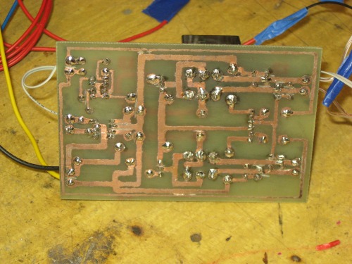
As you can see, I did have a few issues with some lines bumping each other but a cut-off wheel in a dremel and a very steady hand, I was able to tidy up everything.
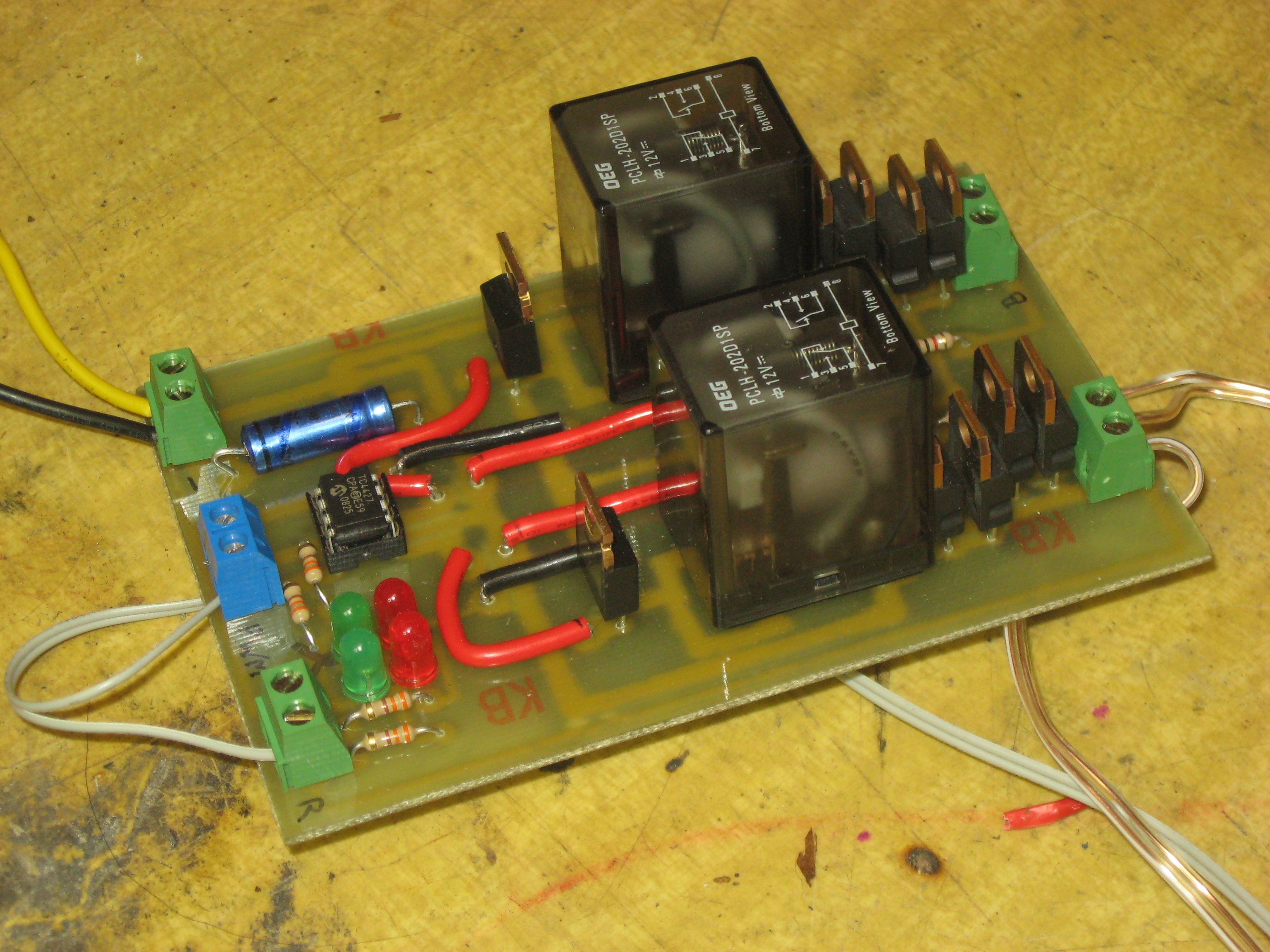
And here she is!

Here you can see all the parts, the 2 green LED's are tied to the PWM input while the red LED's light with reverse.

Once again, much love and thanks to all who helped with this project. At the time of this post (and the video included) is of my first -low current- test. I hope to have some new videos up soon including this unit running the 2 DeWalt drill motors it was built for!


Run 2 Motors, Fwd and Rev with PWM Control

  • Power source: 12V Power / 5V Data

This is a companion discussion topic for the original entry at https://community.robotshop.com/robots/show/big-motor-driver-done

out of curiosty, have you

out of curiosty, have you run into issues with rpm drift(one rotating faster than the oter) for each motor? I ran into a similar issue on my design and contemplated using trim pots , but not sure where it would work on your design,after u1 and before q1/2 maybe? What sort of current was this going to draw again?


Looks very cool!

Current-ly we may be experiencing a problem

Well, it’s pretty cool that it all went together well, making a solid h-bridge. Now for the scary part …

DeWalts? Here’s a quote I’d found from someone using some 12 volt Dewalts in a scale RC tank :

> > My first motor trial was with 2 Dewalt 12v. Tank weight was about 100lbs,
> > the motors would pull about 20 amps straight line driving, stall current
> was
> > about 120amps. Lots of power in a little motor but they got really really
> > hot in a short time. After the fire I upgraded to wheelchair motors but in
> a
> > light tank like a Hetzer you might be OK.

Taken from here : http://www.rctankcombat.com/archive/2005-12/msg00262.html 
There are a few different Dewalt motors, with slightly different specs that appear to be hard to find on the web. 
Maybe you have 24 volt Dewalts, that might be a little better on current due to the different winding, 
and might be closer if running at the 12 volt side, halving the current drawn. Just seems a bit worrisome, 
and something you might have a fire extinguisher around for in testing. 

Fuse on da power connection

Possible help against the hell-fire of over-current : Radio Shack inline fuse holder

With a 15 to 20 A fuse (prob 15 A best) and should be at auto parts stores too.


Sweet

Great board! I know the artys will disagree, but to me, this is further evidence that planning is 90% of the job!!

Well done. Just check the FET temperature the first few times you run it…

Try to implement something in code which disallows the reversal of the motor while it’s running.

Thanks guys.
Very good ideas. First, I would not even consider using this board (at full current) without a fuse -car batteries can turn into arc-welders pretty quick. BOA, I can certainly see the need for a fwd/rev lockout in the code as well as a chunk of code for "ramp-up". Oh, and in terms of the 2 wheels in the video turning at different speeds, I wired them in series to get a 12v load to test -they took turns stealing power from eachother while I was doing my tests. -And if you notice on the board I was using for control, you will see (2) 15-turn trimmers… Nice for trimming wheel speed.

Too cool - 2nd vid
Awesome update, glad to see that operating well. Looks to be a pretty strong starting powertrain for a robot.

Wow: I mean Wow!!You can

Wow: I mean Wow!!

You can really make a big bot with that. If you plan on making something like BoozeBot you could simply have the robot bring you the whole fridge.

I like the way you credit all the people who contributed in your video. Don’t forget to take some of the credit yourself.

Anyway: Nice work.

just one question

who do you choose from reverse/forward?

q3 and q4 of the Schematic connect to the board?

great controller!

@silva
If you look at the layout (not the schematic) you will see 2 lines that start at Q3 and Q4 and trace all the way to the other side. -They follow the very outside of the board and meet together at a screw terminal next to the LED’s. Each one of these transistors gets a 5V signal from that terminal (triggered by a standard “high” output from the picaxe) and then clicks each of the relays. So basically, there is a PWM signal that controls speed for each side (A/B) and a reverse input for each side (A/B). As BOA has mentioned a few times, there is a danger you need to be aware of with this set-up… If you are not careful, you are able to click the relays while the motors are at full speed -there is no safety against this. One must simply be careful to code properly to avoid this issue. In the case of my test videos, I was sure to power down before switching from Fwd tor Rev.

Something else

Just thought of a couple of other things. You haven’t really had a high current test yet. You need mechanical load on there to prove the current. Might be worth hooking an ammeter in series with your motor and rigging something to put increasing torque on the motors. I put a wheel on my motor with a bit of rope looped a few times around it. I could increase the torque by tensioning the rope.

The other thing, voodoobot’s post reminded me that, while my motors spin a similar speeds if they’re both going in the same direction, they both spin slightly slower in “reverse”. Typically, with one motor mounted on each side of a robot, one of them must run “backwards” (relative to the other) in order to get it to go straight.

What I see in my bot is porbably a feature of the worm drive gearbox in the wiper motor and you may not encounter it, but I’d be interested to know.

hey ctc, While doing a

hey ctc,

While doing a search for "and" gate usage, I ran into this site that had a particularly interesting hbridge setup.

http://www.cadvision.com/blanchas/hexfet/index.html

the backlink where I found it was from here:

http://www.x-simulator.de/forum/tronic-s-diy-dual-mosfet-h-bridge-t820-80.html


Possible protections

I’d missed the Update above initially, but saw the shoutbox and messages that something went wrong. Kinda sounds like a FET quit, and did it while being locked on. Grog mentioned here that FETs can fail to being on, when hit with a voltage spike. I’d mentioned here the connection for the flyback diodes to use the FET drain as ground, but failed to implement that in the circuit by following standard flyback connections. Don’t think that is really a problem, but might be something to think over.

FET input protections to prevent the driver from over volting the gate might be to add a zener diode limiting the voltage to 10 or 12 volts. Additionally, a resistor can be placed between the driver and the gate to prevent “ringing” between the 2, though that probably isn’t happening here. The over-volting might be happening if the motors are spiking the voltage enough for it to feed through the drivers and be transmitted to the gate, though it might be expected for the driver to fail before sending the voltage. Something like the OnSemi 1N5349BRLG would be a good zener, connected anode to ground, cathode (bar end) between the FET gate and driver connection. Digikey part 1N5349BRLGOSCT-ND 12v 5w zener, (sold in q10) The resistor between the driver and the FET gate might be a 10 ohm 1 watt type, Vishay NFR0100001009JR500, Digikey PPC10CCT-ND . Either or both of these might help the driver from getting too hot, though it is probably only getting hot being forced to drive a failed FET.

It is also very possible the FET died from getting static zapped on installation, which might allow it to operate for a bit, then fail. FETs can be very static sensitive, as other devices that use them can be but typically have some sort of protection. Sadly it’s difficult to say what caused failure, without hooking up an oscilloscope to watch how the device is switching. Might be as simple as dropping to a 15 A fuse too, to give some headroom and adding a small heatsink to each FET.

Sssllloooww PWM
That h-bridge has 10k resistors that would slowly bleed off the charge from the FET gates, causing a bit of a slow turn off. That wouldn’t allow a very high PWM frequency.

Thanks, guys

I really dunno what happened, I think I have fixed the problem, though… Last night I ordered 4 new FET’s and a couple new drivers. If nothing else, I should now have a few on hand for future problems.

Then again, the order will arive AFTER tuesday, so in reality, John McCain might be president and the world will simply end and we won’t have to worry about fried FET’s… Just nuclear holocaust… Either way I guess I got it covered.

Backwards?
Ya might be thinking of the wrong candidtate, don’t you know it’s the Obama-nation of desolation that brings on the apocalypse?

No comment
"George Dubya." That’s all I have to say. Whetever happens, the wrong guy will win. Let’s debate this elsewhere.

Debate?
Guess smiley faces actually could be helpful in indicating "jokes".

Version 1.1

Hi Chris,

You might want to consider a TVS Diode for protection - I’ve been looking at osmc for a little bit and they appear to have this kind of protection around their FETs. Perhaps a bigger cap to attempt to smooth out some of the shock of inductance?

|x


TVS’s diodes and resistors

Hey Grog,

The resistor diode combo that you see on the gates of the OSMC FETs were for a couple reasons. The resistors were to limit current from the driver, to keep the heat down, and the diodes were there to hasn’t shut down of the FET, to prevent shoot through. There is not upper FET here to have shoot through, so no diode on the gate is needed. A resistor of some sort might be helpfull to limit the current of the driver a little.

The TVS devices are really more useful in the OSMC, as the IRFZ44 has a 55 volt reverse breakdown Vds compared to the voltage supply of 12 volts, where the OSMC was made for a supply from 12 to 50 volts operation, much closer to the 55 volt Vbrdss of those FETs used there.