Big Motor Driver Done
***Update***
Well, it seems I might have smoked something. I am in the process of testing the motor driver, with a load, and using 2 motors. While my "B" channel seems to be working fine, the "A" channel seems to be stuck on. Not to mention, the FET driver sorta burned my finger when it was touched. All this and I have yet to blow my 20 AMP safety fuse! I'm letting it cool off a little and am going to try again. ---I am not looking forward to asking for "purchase authorization" from the wife for more parts!
What started as a simple question about running big motors has turned into 2 threads and over 110 posts.
What has come of this is wonderful submissions from BOA, GroG, Robologist, Krumlink with Rik and others filling in a bunch of gaps and disputing what everyone else has said. I have gleaned what I could from this firehose of posts and decided to go with the BaseOverApex/ Robologist plan. As an overview this is a high power motor driver with logic level inputs for PWM and "reverse", a FET driver chip and FET's for main power switching and 2 high power relays for reverse. Here is the original schematic from the second follow-up post "H Bridge Matrix":
BOA's Brilliant Hybrid H Bridge - Robologist Mod
| BOA's Brilliant Hybrid H Bridge - Robologist Mod | |
|---|---|
| Description | BaseOverApex's design of a great Hybrid H-bridge. The hybrid is a combination of relays and MOSFETs. The relays are for forward and reverse switching. The MOSFETS can accept a high frequency PWM for speed control. This design has been built (not just theory) and is currently powering one of BOA's great bots. Hopefully he will post a version of the PCB art - although it might be good to rework it so that the PIC is not part of the design, as others might be using different methods of control. |
| Original Author | BaseOverApex robologist |
| Built By | |
| Max Current | 15 Amps - limit by relay |
| Max Voltage | 12 Volts to 15 Volts |
| Build Time | 3 Days? |
| Pros | strong, low cost |
| Cons | not quicklyswitchable forward to reverse, limit by relay |
| Max PWM Frequency | |
| Features | reverse flyback diodes, MOSFET driver |
| Parts List | Desig Qty Part# Each Total Dist Description |
| Schematic | |
| BreadBoard | Image:M relayhp B.jpg |
| Gerber | Image:M relayhp gerber.jpg |
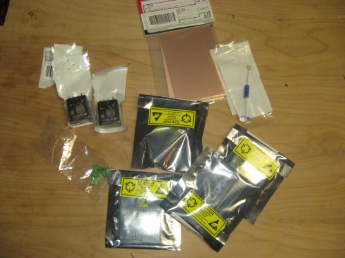
I bought all the parts on the list above, all from Digikey, with the addition of some blank 2oz copper PCB boards and were quite happy when my parts arrived within 3 days!
Next, using PCB123 layout software (which is not only free, but worked quite well) transposed the schematic into a PCB layout. In general, I was able to keep most + runs to the outside and - to the inside. I think I did pretty well, only needing 6 topside jumpers. I must admit, it was a nightmare to keep all the componant's polarity straight as I went as things are mirrored or double mirrored (depending how you think about it) in terms of the top side of the board, bottom side and the fact the transfer is reversed when applied to the board. The picture below is of the final transfer I used.
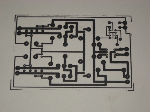
This layout, printed with a printer using ink, was taken to my local copy-shop and Zeroxed as dark as it would go using a standard copier using toner. Next, I ironed the ever-living-shit of the transfer onto my blank PCB board. I was careful to go over each line one-by-one in addition to placing the iron over the whole transfer and putting my whole weight on it.
That would be:
140 Lbs
63.5 Kg
10 Stone
Happy that indeed the shit had been ironed out of it, I soaked-the-crap-out-of-it and then rubbed off the paper.
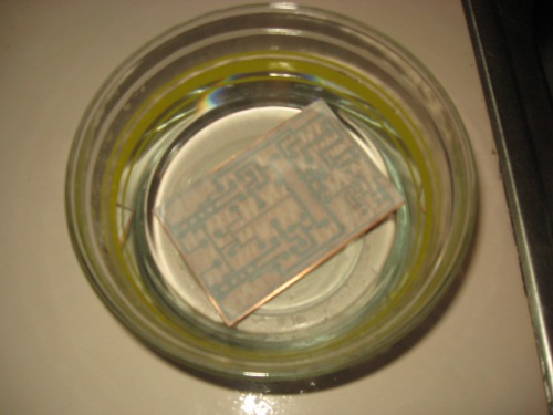
With a little scotch-brite (green scratchy pad (for dishes)) I removed the toner from the circuit lines, drilled and soldered away. The tiny little drill bit came from a model airplane shop, chucked-up in a dremel tool and was done by hand. Also, when setting the parts I seemed to run into a big phatty problem with the layout of the diodes. If you run into the same problem, well, here you go.
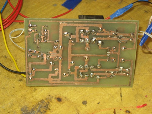
As you can see, I did have a few issues with some lines bumping each other but a cut-off wheel in a dremel and a very steady hand, I was able to tidy up everything.
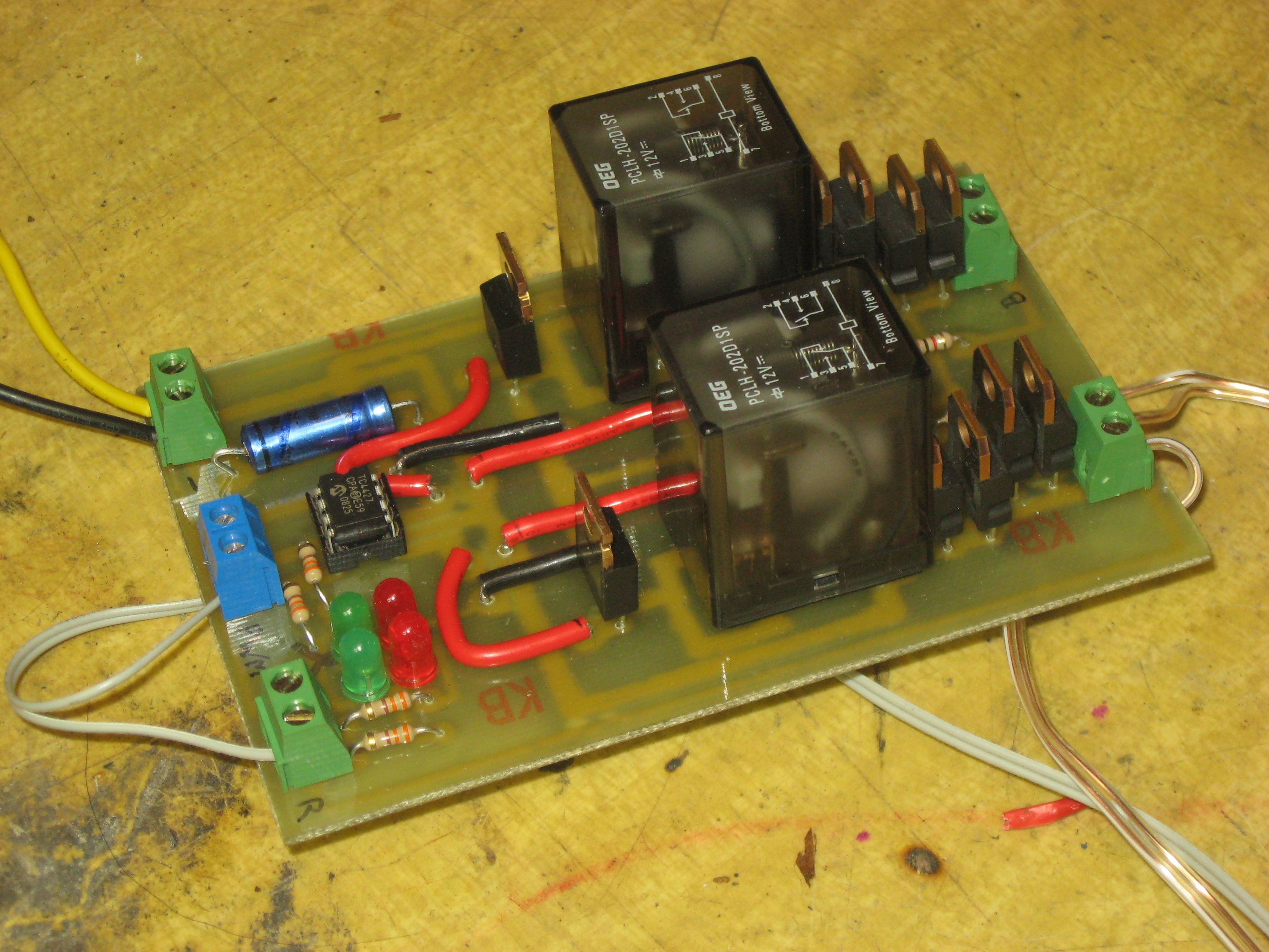
And here she is!
Here you can see all the parts, the 2 green LED's are tied to the PWM input while the red LED's light with reverse.
Once again, much love and thanks to all who helped with this project. At the time of this post (and the video included) is of my first -low current- test. I hope to have some new videos up soon including this unit running the 2 DeWalt drill motors it was built for!
Run 2 Motors, Fwd and Rev with PWM Control
- Power source: 12V Power / 5V Data


