Big Chaser


2008-05-18

The deal is, this 'bot will (hopefully) follow me around. For me the challenge is to do something bigger than Lego scale.


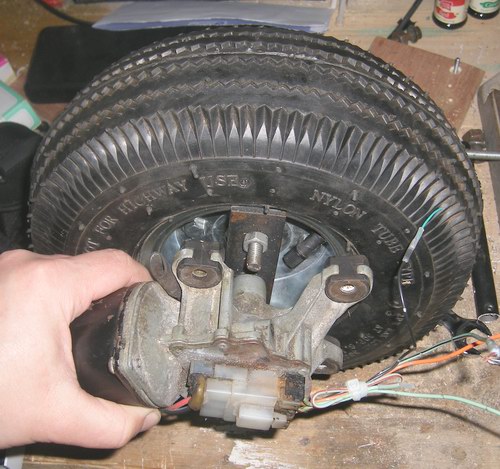
So far, I have attached a car windscreen wiper motor to a pneumatic sack truck tyre. It's going to be BIG. The clue is in the name.

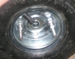
The wheel consists of two metal plates which are bolted together. I made a couple of extra long bolts and bolted a bit of mild steel to it. Bolted to the middle of the bit of steel is a windscreen wiper motor from a Nissan Micra.

Next weekend, I'm off down to the junk yard / scrap heap / scrappie (depending on your geographical location) to get another wiper motor. When I have two fitted to some sort of a chassis, I'll report back.

I envisage something powered by a couple of big FETs under PWM control with DPDT relays to reverse direction.

2008-05-24

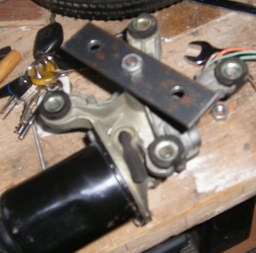
Got my second wiper motor today. Found another scrap Nissan Micra down at my second favourite place (second only to the electronics store). Got the motor for $30. That's Not too bad. I could have haggled him down to $20, but I was in a hurry.

Remembered something else about these motors: They have a momentary switch internal to them which gets a hit every rotation. Cool! BUILT-IN SPEED SENSOR!!

2008-06-01


It would appear that my eldest son has decided that my new robot platform would make an excellent trailer for him to tow his younger brother behind his bike. As soon as I obtain custody of it, I'm ready to retrofit the motors.


I may or may not keep the plastic seat which has been bolted on top. At this stage, I'm thinking "radio-controlled pram" or maybe just automatic pram which follows me around. At last - a robot with a purpose!

2008-06-09

Built a new platform. It turns out the trailer is proving popular. New photo above. Hit a tiny problem. Not a showstopper. I mentioned a built-in SPCO switch in the wiper motor. I had hoped to use it as a rotation/speed counter. The problem is that the the motor "ground" wire is also the "normally open" contact of the switch. The plan was to connect the "normally closed" side of the switch to ground and run the switch common to the pic as an input (with pullup resistor enabled). Great when the N/C switch is closed, but for a brief second each rotation the switch changes over and the motor "ground" becomes switched into the PIC. Not a real problem for the PIC and if the motor is running "backward" (ie, ground is powered), the PIC will be able to increment a counter based onhe rising edge. HOWEVER, if the motor is running "forward" (ie ground is grounded) then the pic will detect no change.

Pisser.

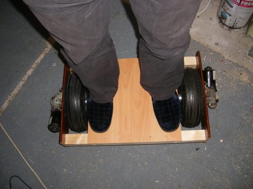
BTW, this is 95kg (that's about 210lbs for our American friends) of ME

standing on the robot chassis. Early experiments show that it will easily plod along with a 25kg child sitting on it!!

I'm off to work on the circuit. I have a provisional one, but I want to separate the motor 12V from the TTL 5V onto two different PCBs.

2008-06-22

I thought about it a bit more and decided the drive board needed its own logic supply. (See next post.) The reasons will become clear as I explain further my modular robot electronics concept.

2008-07-07

New photo, new video. OKay, I wanted to prove that the controller board worked, so I programmed it to read the outputs from a radio control receiver. These are converted to 2's compliment byte values in the PIC and fed to the PWM controllers. The result is a pair of radio controlled windscreen washer motors with pneumatic wheels.

The platform currently has a "training" wheel. It seems likely this will be a feature for a while. I want to concentrate on the modular concept first, the person following, then the balancing act.

I'm very very happy with the motor control board and now I also have a good, usable routine should I ever build an I2C radio control receiver module.

Follow me carrying a 30kg child.

  • Actuators / output devices: NIssan Micra windscreen wiper motors.
  • Control method: Completely automagic.
  • CPU: Microchip PIC.
  • Operating system: BOA-OS
  • Power source: 12V motorocycle battery.
  • Programming language: PIC RISC assembler
  • Sensors / input devices: Ultrasonic sensor with servo sweep. May add an accelerometer as a safety device.
  • Target environment: outdoor, paved areas. Off-road would be nice.

This is a companion discussion topic for the original entry at https://community.robotshop.com/robots/show/big-chaser

Control Hardware

MotorControllerSchematic.gif

The motors selected are car windscreen wiper motors. (I made the mistake a while back of telling a colleague I’d used a starter motor. D’uh.)

They are great. A good bit of torque. Experience (I put one in my son’s pedal tractor a few years ago) tells me that one is JUST about anough to propel 20kg of small child across a car park.

H-bridge control is out of the question. I know the theory of doing it with a pair of N-channel and a pair of P-channel FETs, but the logic propogation delay worries me and I don’t want my FETs to go into “one-time smoke mode” (a phrase coined by someone else on this board).

A drive solution using 100% relays is a no-no. The Mark I tractor experiment used relays only and we discovered that when he pressed the “go” pedal, it shot forward and he shot backward. The equal and opposite was true when he released the “go” pedal. I am opting for two relays, though: one per motor to reverse the current.

I’ll be using a FET PWM drive. There are two reasons: 1) ramp up the speed so it doesn’t instantaneously go to full power and 2) these motors don’t run at the same speed forwards as they do backwards! It’s irritating, but if I make the two drives mechanical mirrors of one another, one of them will be forced to run inefficiently by the controller. My FETs are sinking 40Amps and these motors will draw about 12 Amps at 12V when stalled stall. I’ll be experimenting with a frequency independent technique called a “bit-twisted PWM drive.” (Watch this space.)

MotorControllerTracks.gif

Speed / positional feedback from the motors is likely to be derived from a zero detent rotary switch (12 positions per rotation) on each wheel hub. This is not the highest resolution in the world but it will do for now. The 2-channel FET / relay board will be under I2C control from a host microcontroller. Elsewhere details of the motor controller I2C module will be published as part of an open source experiement. (Link to follow.)

The max speed with 64RPM motors driving a 270mm wheel (no load) will be about 2mph. It’ll barely keep up with me at walking speed. That’ll be PWM’d down to stay a fixed distance AWAY from whoever it’s following. Might have to get a bit more voltage from somewhere and increase the speed a bit.

2008-06-22

Finally, I’ve got around to finishing my prototype controller circuit. It follows on from an idea I’ve been throwing around recently for a modular robot. It was encouraged by iDaniel’s post here. Once programmer, the motor controller won’t do anything unless instructed via teh I²C bus.

This version does not support positional / rotational feedback from teh motor. It’s really only a beta version to get the platform to do SOMETHING! The Eagle CAD auto router had difficulty with it so I did some of the routing manually. I suspect that when I add feedback, I’ll been to go to a double-sided board. I hate these 'cos I don’t have a good system for aligning the two sides.


2008-06-23

Here’s the PCB going into the etchant. Yes, it’s a chocolate chunk ice-cream tub. Also, there’s an airstone from a fish tank in the bottom of it attached to a pump to produce bubbles and keep the etchant circulating. The mix I’m using is not terribly harsh, but with the bubbler it

MotorConPartial.jpg

etches a board in about 20 minutes!

(I promise I’ll do a howto on making PCBs when I get around to it. I think I have 10 minutes spare in September next year.)

This evening I got the board partially populated and have started to code the firmware. Mostly, it just tests the board.

2008-06-29

PCB is now partially populated and tested (one channel only). Software is partially complete (direction control and almost PWM speed control). No I2C comms routines yet. Yes, that is a FUSE. They are used to revent the smoke escaping from your electronics when you do something silly. I will write a HowTo on fuses later.

2008-07-03

Board is fully populated and fully tested. It looks like the photo above, but with an extra relay, FET and transistor. I got some sexier heatsinks for the FETs. I have 2-channel bit-twisted PWM at 434Hz with direction control over a range of 10 speeds (including 0=off). The fist 4 of these don’t move, they just cause audio noise from the motors. There’s not enough juice to get them moving. I2C slave code is started. Need to build a “master” to talk to it.

2008-07-14

TransFET099.gif

Had to do a bit of rework on the board. It was OKay for short periods, but was getting quite hot. With a lot of help from jip, I cam eup with this FET drive. It seems one requires to pull the gate above the drain voltage. This may be called "saturation." I'm no expert and my terminology might be rubbish.

I don't know if my solution is only working by luck but with the motor on the drain side of the FET, I think that the resistance of the motor means that the voltage at the drain is lower than the 12V being supplied to the gate by the transistor. I'm pretty sure this is a requirement of the FET.

Either way, I appear to have max voltage, acceptable current and no heat.

If anyone understands FETs and can explain them in BoA-speak, please do so.


Todo:

  • Implement as I2C slave.
  • DC for main battery voltage measurement.
  • Add ramp up/down speeds to remove starting jolt.


Person Detectors

PIR was briefly considered as a person detector. The problem is that if the bot is moving, all the PIR will detect is that stuff in front of it is changing. It has been argued that we could periodically stop the bot and have it “look” but it would only “see” what had changed since it stopped.

Ultrasound was also briefly considered. It’s facing some opposition, but it works on automobiles and I think it has a fighting chance.

Anyway, the first use for this platform has changed. I think it’ll remain a 2-wheeler and that should be interesting enough.

BOA - great video! Very

BOA - great video! Very smooth action (better than my driving). Now for some wildly erratic questions.
1. Why did you mount the motors on the outside vs inside of your frame?
2. Why are you using a relay vs a full 4 FET H-bridge?
3. What kind of RC are you using and what range does it have?

Is the drive train tight enough to make it balance? This video might give you some ideas. The fact it can get itself up, if it falls over is a big plus. Now it just needs to push the vacume around the house.


Erratic Responses

1) because the wheels came with built-in bearings, which I wanted to make use of. I have put an axle through them. I considered putting the axle on the outside of the frame, but decided that if I stood on it the frame would twist, so the axle runs the whole way from one side to the other.

2a) I don’t have any P-channel FETs.

2b) I would prefer an H-bridge solution, but the only schematic I have only carries 4 Amps. I bon’t like mechanical devices where electronic ones would work better (and make less noise).

3) It’s a really old Acoms 2-channel for R/C cars circa the 1980s. I’m too yeller to find out what its range is but it is at least 200 metres.

There is absolutely no slack in the drive train and balncing is the ultimate goal. THIS one is brilliant. Check out his motorised unicycle!!

BOA: You are going to need
BOA: You are going to need some huge ass FETS to drive those motors! Dont forget about stall current too.

Nope.
I have some mediocre FETs currently controlling the speed of the motors. The relays just switch the direction of the current.

I did not have audio - is

I did not have audio - is the 400 Hz irritating? Is it loud - I imagine some of the sound depends on the physical makeup of the motor.

I have a full FET H bridge - I’m driving it with a 555 timer @ about 144 Hz - its kind of “not so pleasant”, maybe its time to move over to a pic :wink: .

I saw the little balancing bot before - it went down a high incline hill with dirt and loose rock and did not fall over (very impressive) - the ball bot is a neat concept too. It does not have to “turn” to go in any direction at any time.

Great project!


Driving force
What current can your H-bridge sink? Do you have a schematic I could copy?

2a) You can do an H-bridge

2a) You can do an H-bridge with all N-channel FETs but of course you would have to produce some negative voltage and feed 0V and -V to the motor and +V to turn the high sides of the bridge on (at least I think that’s how it’s done).

2b) That’s interesting. I always thought that the amount of current an H-bridge could sink only depended on how much current the transistors and the snubber diodes could handle and not on how the schematic was designed. I would be very pleased if you could elaborate and explain what other considerations there are.

Big chaser looks like a really awesome platform!

Let me give you a not so

Let me give you a not so short summation of the long story. I decided a long time ago I wanted to build a “useful” bot. I had created ones that walked around in flames and ones that scared co-workers. I-robot’s roomba is a pretty nifty floor cleaner, but i want something that will use my vacuum cleaner to clean the floor, or pick up my underwear, or run down to the grocery store and pick up some beer (get a wife has been the typical comment to that - but after 20 years of marriage, that solution does not always pan out).

I figured I needed something human size with human strength, if it’s going to do human work - so a year or more ago I started Loki. I’m also interested in putting it together from off the shelf parts for the smallest amount of money. I was looking for a form factor which was pre-built to the dimensions of a human. The first thing I thought of was “electric wheelchair”. I found one shortly after on craigslist.

This wheelchair is for a large person - and is powered by 2 (yes 2) deep cycle marine batteries in series. Next was a discovery in safety electronics, while trying to interface with the existing controller, I learned 3 things.
1. The safety electronics in wheelchairs are very impressive
2. The guts of the controller use 8 X IRF 2804 MOSFETS
3. You can control even more current by running the MOSFETS of the H-Bridge in parallel (can’t do this with transistors because of the way heat affects current flow)

I fried the controller eventually and decided to make my own with 8 (4 for each motor) 2804 MOSFETS. Initially it did not have PWM - that was a big mistake. Then I tried doing the PWM in software (another big mistake - this manifested itself as erratic speed because I wasn’t using realtime Linux and the task scheduler would get swapped with another task) - it was kind of a dumb process to tie up the cpu anyway. Another scary thing was parallel ports on PC do not stay low on boot up - (or there is no guarantee they do) - if your controlling your bot with it - then on boot the whole thing can lurch around in convulsions.

I got disgusted with the whole thing and started searching on the web for motor control schematics. I found a couple good ones, but unfortunately most were low current. Then I hit a gold-mine - OSMC Open Source Motor Control - it can sink 160 Amps CONTINUOUSLY ! It’s in its 4th revision and comes with a great number of features (including overload protection).
Here is the list of parts and the artwork. I’ve had the pleasure of talking with Chris Baron who is a nice guy & founder of the project.

You would figure I actually built one of these … sadly no. I believe my electronics manufacturing FU is not as strong as yours. So I ended up buying 2 “Simple H-Bridges” from Mr. Baron. I added a 555 PWM generator and am now controlling the motors through a NI DIO-96 PC board from ebay - (guaranteed low ttl voltage on startup).

I’d be curious to know what the people with strong electronics FU think of OSMC . I’d like to build one, but with limited time I’ve decided to concentrate on ranging, mapping, object detection, and remote tele-operation for Loki (there are only so many hours in the day - and some of which I’m not working on robotics, but doing more mundane chores like picking up my underwear off the floor)

Hmmm…

Yes. The guys at OSMC appear to have done just that using a dedicated driver IC.

For some obscure reason I had it in my head that the drain side could sink more current. Having thought more about it, this clearly cannot be the case as the current must also travel through the source. D’uh.

…but I’m no electronics expert and I bow to superior knowledge. So, I would be very pleased if I could elaborate and explain what other considerations there are!!

Nice

I remember you told me the wheelchair / NI story before.

I like the board. I would leave 12 of the 16 FETs out in my case!! I only need a 10A controller. I recokon I could etch the PCB easily enough.

The circuit for the simple controller is identical to that given in the data sheet for the half H-bridge driver used! So, you’d like tothink it would be of an acceptable standard!

Why are the legs on fire?

dramatic effect - it was
dramatic effect - it was actually intentional, although i’m not sure if anyone believes me

I have your “follow me” problem figured out!

It seems you just need a couple of these:

http://www.pololu.com/catalog/product/702

Just stick one on the robot and as for the other…

Make yourself a belt, stick one of the N,S,E and W led’s and sensors on the front, back and each hip on the belt. You will have a little battery pack and PC board to stick in you pocket but that’s it! --Should work great!

www.rocketbrandcustom.com baby!!

Hmmmm…
The trouble with me is when I see something like that, I just want to make my own…

I know!

I agree, but never the less, 4 (or more) sensor/transmitter sets mounted on a belt, (yes, let me toot my own horn…) is a great idea. I mean, none of this motion detector stuff or some crazy bunch of code to get a sonar sensor to "find an edge" stuff. -Just a silly belt with doo-dads sticking out! KISS!

AND!!.. (This said in a cool echo God voice) The one who holds the belt, holds the power!

www.rocketbrandcustom.com baby!!

FET heat problem

Ok, communication through the shout box can be somewhat strange so I’ll just post here instead.

Just to recap: BOA shouted that he is using FETs rated for 40 A and that they get very hot when running 10 A motors, and this seems a little strange to me.

After checking out your schematic on the motor controller on this page, it seems that you’re driving the FET gates directly from the PIC which I would guess means that the maximum voltage at the gates are ~5V. Since you’re driving the n-channel FETs as switches to turn a 12 V potential on and off, you should use 12 V to turn them on and 0V to turn them on. If you use less than 12 V to turn them on, they will only be “half open” and the resistance across the drain and source (VDS) will be far greater than when fully open and so they will dissipate a lot more heat.

You can use optocouplers to bridge between the 5V from the PIC and the 12V from the motor voltage, but these have an upper limit to how fast they can be pulsed.

Bother

Ah, bother. This is a feature of FETs which I never understood properly. Is it the case that the drain/source voltage can only equal the gate/source voltage?

I don’t really get this. I thought the FET would operate like a big switch if I supplied the +12V to the motor direct and used the FET to periodically ground the motor.

Assuming I’ve understood you correctly, couldn’t I just use a transistor to open the FET gate?connect the base to the PIC, the emitter to the FET gate and the collector to +12?

1) Yes when using n-channel

1) Yes when using n-channel MOSFETs as switches I think you would want turn it on with a voltage at least as high as what is seen on the drain. If you’d like to read some stuff on how these things work , try wikipedia and search for “mosfet” - great description although a bit cryptical at times.

2) Well it is in fact doing that right now, but it’s just getting a wee bit too hot :-). As far as remember it has to do with the n-channel not forming tight and narrow when the gate-source voltage is lower than the drain-source. I’m not really an expert on MOSFETs though.

3) I would definitely try that solution just to see if it works - but again I’m no expert. BJTs are current controlled whereas MOSFETs are voltage controlled and the MOSFET gate is a small capacitor so after a very short time when capacitor is charged, there will flow no more current into the gate. I don’t know if it’s a problem or not.