

About the Project:
Initially, the project was a joystick for a human powered submarine. Because of the nature of the submarine, a small battery had to power both motors and logic. On top of that, the joysick was attached to our reader through a really long wire (~10 ft) and all of our values came out very noisy. We built this circuit to compensate for noise from the motors and the wire, and I thought I'd share it here.
Disclaimer:
Although this design was originally for a submarine, I removed a lot of other complications that allowed this circuit to operate fully submerged. Again, the circuits in this tutorial cannot safely operate underwater. Additionally, this guide has been rewritten using an Arduino as an example board and was originally written for readers with little experience with electronics.
Background:
We, my teammates and I, have written this so that readers do not need much experience with electronics, but we do expect readers to have experience with joysticks and basic electrical schematics. There are plenty of other getting started guides out there. Quick Background: Most analog joysticks are just just a potentiometers (resistor whose value changes based on position). Joysticks usually have two potentiometers, one for the X, one for the Y. The joystick is then usually attached like the Typical Joystick to act as a voltage divider and then read the value from the potentiometer wiper. Good example joystick (https://www.robotshop.com/en/adafruit-mini-joystick-sensor.html)
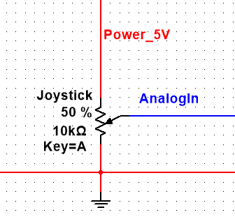
Typical Setup:
Usually, a joystick is used like a voltage divider connected to some filtered connection like an Arduino 5V pin. AnalogIn typically connects to one of the Arduino's analog ports where
AnalogIn = (Power_5V * Rx) / Rj = 5 * Rx / 10K
Rx is the position of the joystick. This equation is actually a bit deceptive. Actually, the resistance between the wiper blade and the grounded terminal on the potentiometer hold our position information. AnalogIn from an Arduino's analogRead() is a voltage, not a resistance. The equation works in the typical case because V=IR. Since the current in this setup is constant, 5=I*10K, the voltage is equal to a scaled version of the resistance. Since analogRead() scales the value anyway (0-5V to 0-1023), the point does not matter in this case, but will matter for solution 2.
The Problem:
This design is great as a basic setup, but if you need to connect this to an unfiltered line (like a battery) that also has to power a motor, the motor causes noise on the power line, which an Arduino picks up. Then if your Arduino is connected to servos (position controlled motors), you can get some servo jitter (moving back and forth a little bit). There are algorithms to correct for this, but if the line is exceptionally noisy, they aren't quite as effective.
The Model:
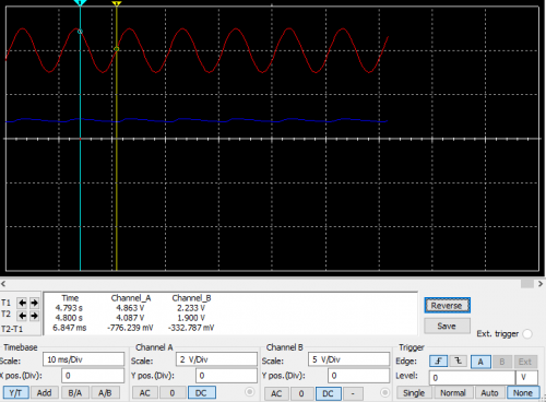
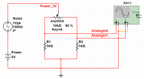
For our simulation, we used the model below. We have a 5V power source modeling our battery, a potentiometer modeling the joystick, an oscilloscope connected to analog in modelling our Arduino, and an AC power source 1V peak with a -1V offset. The AC source models noise, giving our us a signal that ranges from 3V-5V.
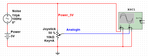
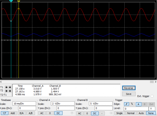
As you can see from our oscilloscope output, we have about 1V noise when our joystick value doesn't change.
Solution 1)
Add a filter! Easy enough right? This is usually done with a capacitor, which smooths out noise quite a bit. Unfortunately, we don't know what the rest of our circuit is connected to, and we don't really want anything else drawing power from our filter capacitor, so we added a diode. This way, once our capacitor charges and our noise dips below 5V, no current flows through the diode to the rest of the circuit.
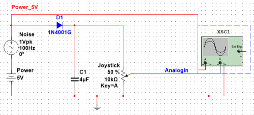
As you can see, we still get a bit of noise, but now its only 300mV. Of course, you can add a larger capacitor, but whats the fun in that? Plus, if the line from the capacitor to the joystick or AnalogIn is really long, you still get line noise :(
Solution 2)
Looking at the voltage divider equation, no matter what, we are dependent on Power_5V actually being equal to 5 Volts for our joystick to operate correctly. Even with the filter, we still need our capacitor voltage not to change in order to get an accurate read. Instead, why not make a circuit independent of the voltage on our power line?
Now, remember when I mentioned the position value is a resistance, not a voltage? This becomes much more important here because our current is not constant with position. As a result, if you look at the analogRead() of either AnalogIn0 or AnalogIn1, they show a sine wave. Instead, what we do here is make our measurement independent of Power_5v.
AnalogIn0 = Power_5V * Rx / (Rx + R1) //eqn1
AnalogIn1 = Power_5V * Ry / (Ry + R1) //eqn 2
Rc = R1 = R2 //for ease
Rj = 10K = Rx+Ry //because Rx and Ry are the resistance values between the wiper and each of the other terminals
By setting eqn 1 and 2 equal to one another and plugging in Rj - Rx for Ry, we get
AnalogIn0 * (Rc + Rx) = AnalogIn1 * (Rc + Rj - Rx)
Solving for Rx: Rx = (AnalogIn1 * Rc + AnalogIn1 * Rj - AnalogIn0 * Rc) / (AnalogIn0 + AnalogIn1)
Since Rc, Rj, AnalogIn0, and AnalogIn1 are known or measured, we known Rx. This also means our position is totally independent of Power_5V. As long as this circuit has adequate power, noise on our power line doesn’t effect our measurements.
Here’s an Arduino function for this measurement:
int calculate(int AnalogIn0, int AnalogIn1) {
int Rc = 1000;
int Rj = 10000;
int val = ((AnalogIn1Rc)+(AnalogIn1Rj)-(AnalogIn0*Rc))/(AnalogIn0+AnalogIn1);
return val;
}
An output waveform doesn’t do us much good here since the value of Rx is a function of Rc and Rj as well as AnalogIn0 and AnalogIn1. Instead we exported simulation data to excel and found we had perfect values. There was absolutely no error using true voltages, but there was some error due to round off from the Arduino’s analogRead(). Maximum and minimum measurements, which have the greates error, are shown below.
| V1 | V2 | AnalogRead0 | AnalogRead1 | Calc. Rx | Calc. from analogRead() |
| 0.4 | 1.999999999 | 81 | 409 | 9000.000001 | 9016.326531 |
| 0.499997157 | 2.499985787 | 102 | 511 | 9000.000001 | 9016.326531 |