Hi All,
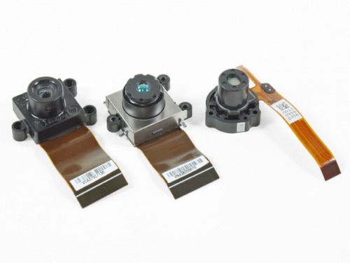
I'm in the process of acquring a CMOS camera, and I'm looking for a way to distance the camera from the circuit board that it is connected to. I havent' counted the pins, but it looks like the LCD flex cable might have approx. 20 pins (+ or - 5 pins).
I don't yet know their spacing. The options I'm thinking of are:
1. Buy a wide LCD extension (or regular) cable and cut it down to match the number of pins. The issue here is that the extension cables usually have an end that has the wire/pads exposed, which i can hopefully solder to. But its other end terminates in some type of connector. If i cut off that connector, i'll be left with no exposed pads to solder to. Maybe I can use a sharp pen knife to cut away the protective plastic and expose the flat wires that are sanwhiched in between?
2. remove the existing flex cable and solder wires to its end, and the actual connector on the PCB.
3. remove the connector from the PCB and solder my own wires between the pcb and the connector. This might be an ok solution because i'm getting better at removing SMD or multi-pin components off of PCBs. The method i'm using is adding more solder to areas that have already been soldered, heating the whole area up and simultaneously trying to pull the piece out of or off the board. I can then use solder wick to removed excess solder from the parts. But in thinking about it, i'm not sure if i want a whole bunch of hot solder around the plastic connectors that i'm trying to remove. Perhaps i can use a fine tip on the soldering iron and pry off each pin on the connector one by one.
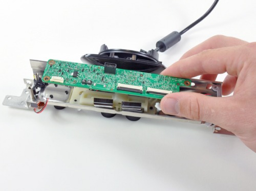
Here's some pictures of the types of camera that i'm trying to extend the cables of, and also of the board that they were connected to.


If anyone has any experience with extending lcd flex cables, or even has any theories of how this can be accomplished, it would be much appreciated. Thanks!
Thanks!
Hi Duane,
Hey thanks for all of the information and the link to the boards. Firstly, i didn’t even know those types of boards existed, or even the name of the “zif” cable, but now i do and can explore the vast array of types and connectors.
And I only came across chipquik’s desolder kit on youtube yesterday, and its good to know that it actually works from someone who has robot and circuit fabrication experience. I will definitely give that a try.
I’ve only scratched the surface of PCB design software, and realized that there are a lot of rules to follow (spacing of the circuit “lines”, avoiding right angles). But it is something that i want to get into soon so that i can make a new version of my balancing robot more compact.
And I hadn’t thought that extending the wires might cause the system to not work well, possibly due to noise introduced on the lines. There is a thing I learned in a live sound set-up class, called XLR. This system used in professional audio uses 3 wires to connect a mixer to a microphone for example. the microphone will send out:
1. an in phase signal
2. an 180 degress out of phase signal
3. ground.
So at the mixer’s end , it will reverse the 180 degress out of phase signal and combine it with the normal one to get the signal that will be used. Now as the signal travelled from the microphone, noise was introduced into the regular and the 180 signal equally. So when the 180 signal is reversed, its noise is now 180 from the normal signal’s noise, and they “cancel” each other out when the signals are combined. These are analog signals though, and i’m not sure what the digital equivalent of this might be.
Thanks again!
@ DuaneThose are a lot of
@ Duane
Those are a lot of examples of digital balancing! I remember MIDI now that you mentioned it, but I had no idea the others were also balanced. There are quite a lot of wires and interfacing, as you mentioned, may be the best option.
@ bdk6
I want the cables to be about 4 or 5 times the length that they are currently, perhaps 15-20cm total. My aim is to put these cameras into a robot head, but I want to avoid “wide-head syndrome” because the circuit board is wide. I was thinking to put the circuit board into the robot’s torso, and run the cables into the head which has the 3 cameras. Using balanced lines does seem like a lot more work and hardware than i had planned, i might just use the method of extending the cables.


