Benchtop power supply from ATX computer power supply

I was tired of wasting batteries while testing my robots and other circuits, and having to dig out voltage regulators every time I needed 5v or 12v for a circuit, so I started thinking of alternatives. I looked into commercial benchtop power supplies like this one, and they're definitely nice, but for 99% of my work, I don't need a fully adjustable voltage and current -- usually I just need one of a few different voltages (3.3v, 5v, 12v, and maybe 9-10v to simulate a 9v battery).

I realized that ATX computer power supplies already put out all of those voltages, and I had one sitting in my closet, so I looked online and sure enough, there's a bunch of guides explaining how to modify an ATX power supply for use as a benchtop power supply. All you need is a power resistor, an LED, and some binding posts. And the cool thing is, these six voltages (-12v, -5v, 0v, 3.3v, 5v, 12v) actually combine to provide a whole lot of different voltages, once you realize that your circuit's 'ground' doesn't necessarily have to be at 0v. I can get 24v (-12v and +12v), 17v (-5v and +12v), 12v (0v and +12v), 10v (-5v and +5v), 8.7v (+3.3v and +12v), 8.3v (-5v and +3.3v), etc.

I won't go through the whole walkthrough and explain every single step, since there's plenty online (I found this one and this one particularly useful), so I'll just post my pictures. IMPORTANT: If you build one, be sure to pay attention to the step where you discharge the power supply's large capacitors by either letting it sit unplugged for several days before opening it, or using a power resistor to short one of the positive lines to ground.


Pretty sizeable current capabilities. Of course, I only used one or two wires per rail, so I wouldn't try to drain this much.

The innards. The upper fan was originally mounted inside the case, but I mounted it on the outside to make room for my wiring.

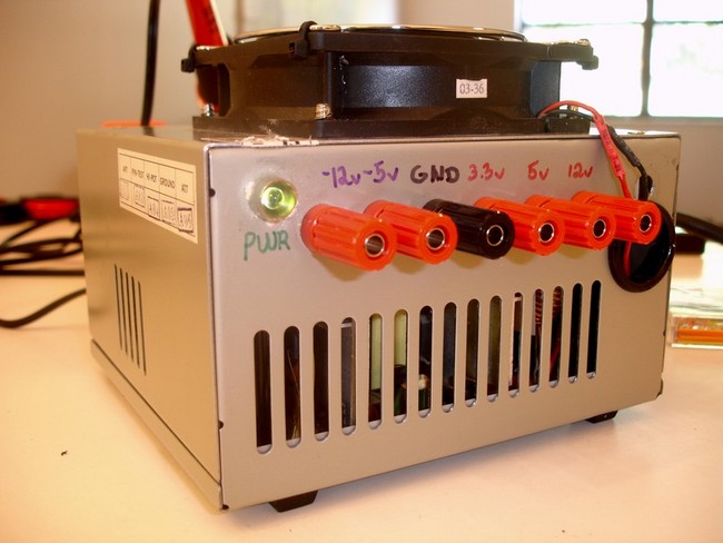
I would have preferred to solder the wires to the binding posts (because then I could have used more wires per rail), but those binding posts didn't take solder well at all. The thinner wires on the +5v (red) and +3.3v (orange) posts are voltage sense wires -- they have to be connected in order for the power supply to work. The gray wire goes to 5v when the output power is stabilized, so I wired it up to a green LED to act as a power indicator light.

Unneeded wires trimmed away.

ATX power supplies have a 'soft' power function -- the green wire tells the power supply to turn on or off. I shorted it to ground to keep the power supply on as long as the switch on the back is in the On position.

ATX power supplies apparently also need to see a minimum load in order to stay on, so this 10 ohm 10W power resistor takes care of that. Another option would have been to use a 12v light bulb for the power indicator instead of the LED.

The completed power supply.

My workspace (tidied up significantly).

Is that a Jameco Valuepro
Is that a Jameco Valuepro breadboard? If so I have the same one :slight_smile:

Neat!! Thanks!
Neat!! Thanks!

It sure is :slight_smile: I just picked

It sure is :slight_smile: I just picked it up for use with this power supply, so I don’t have any experience with it yet, but I’m sure it will be much nicer than the little business-card-sized breadboards from Radio Shack I’ve been using so far. I’d like to get two more power rails for the outsides though, especially now that I’ve got all these different voltages so easily accessible.

Dan

Great idea! I think I’ll

Great idea! I think I’ll start working on one as well -


It’s a beast!

Is that a 44mm chipboard octagonal melamine faced coffee table from IKEA?

Heh. Seriously, though. That PSU’s a beast. I specially like the notion of -ve power supplies. They are a pain to “cobble up”. Lo and behold: look what I just found…

I was looking for a purpose for it. Are we certain all the various bits of the PSU are happy enough to carry on working even if there’s no load on them?

Haha, I got that dining room

Haha, I got that dining room table for free when my friends moved and couldn’t fit it in the moving van :slight_smile:

Yeah, this PSU is relatively heavyweight to be sitting in a closet – I had it in my computer when I built it, but when I added the 5th hard drive last year, I found that the 400 watt PSU just wasn’t up to the task anymore, so I upgraded to a 700W one (four separate 18A +12v rails, arr arr arr). But I’m sure even a bargain 150W PSU from an old Pentium would be plenty for the average amateur roboticist’s needs.

From what I’ve read, as long as there’s some sort of load on it (provided by that 10 ohm resistor), the PSU will be fine. Again, there’s enough walkthroughs on this conversion out there that it sounds like plenty of people are doing it, so they must not be running into too much trouble. Well see how it goes, of course. I just finished building it, so I haven’t actually used it to power anything yet. I’m looking around the house trying to think of a circuit I need to power :slight_smile: I thought my motorcycle-powered garage door opener circuit needed troubleshooting, but I tested it again and it seems to be working just fine. Dammit.

Dan

BTW, I did notice that the

BTW, I did notice that the negative rails support much less current than the positive rails (as you can see in that sticker above), so that’s something to take into consideration if using them for a project.

Dan

Ripple?
Any idea what the ripple is like?

Not a clue. I don’t even

Not a clue. I don’t even know how ripple voltage would affect my life, so I won’t know how to tell if I’m seeing it or not :slight_smile:

Dan

It’s pretty small - I
It’s pretty small - I measured a pc supply on the scope several years ago just for giggles, and the ripple was suprisingly small. The formua I seem to rember using as Vr=I/CF where Vr is ripple voltage, I is circuit current, C is your filter cap (or caps) and F is Frequency (at the rectifier). You can measure the freq on the scope, or just figure it will be about 2X the mains.

Below zero
I’ve only ever had to use -ve voltages as a Vref anyway. Anyone know if this is reasonably typicaly? Is there stuff that needs to draw real current from a -ve supply?

Hey, very nice and useful

Hey, very nice and useful project!

What is it they say… “With great power comes great responsibility”! If you’re using this type of power supply for your projects instead of say batteries, you’d better be very careful with your design, since the supply will not be as forgiving when you accidentally make a short circuit or accidentally hook yourself into the circuit. 38A @ 5V, that’s serious business! …so take care out there :slight_smile:


38A 5V
I don’t imagine the +5V is desperately stable at 38A. Anyone have a 200W 0.2 ohm resistor handy?!?!?!?

That’s true. I bought a 3A

That’s true. I bought a 3A fuse that I was going to install on the 0v line (realizing that it wouldn’t protect me when I’m connected to other posts like -5 and +5, but that’d be relatively uncommon), but it turned out that I don’t have a big enough drill bit to make the hole it requires. I left some slack in the ground wire so that when I find and buy the appropriate bit, I can open it back up and add the fuse.

Dan

Laboratory PS
For those who doesn’t have spare PSU, or are just lazy, This labolatory DC Power Supply costs here around 20E which is a price for PC PSU.

Good point

…and if you’re in the UK and lazy, Maplin have this. (Link will be removed after 05-Aug-2008 as this is a sale item.)


2 voltages at the same time
I would like to use this power supply to get 24V (-12 and +12) and 3.3V (3.3 and 0) out at the same time. Do you think it could be modified easily?

If you’re referring to the

If you’re referring to the ATX power supply, all voltage rails are powered simultaneously, so yes, you can use both at the same time – you just need to keep it within the current limits specified for your PSU. It seems that the negative rails don’t provide much current at all, so you need to be careful there, or you’ll activate your PSU’s overload protection circuitry (assuming it has one like mine does – if it doesn’t, then maybe you’ll just set something on fire instead :).

Dan

A lot of PSUs have the
A lot of PSUs have the current limits for each rail listed on the side of the case - if not, you’ll have to look up the part stats online.