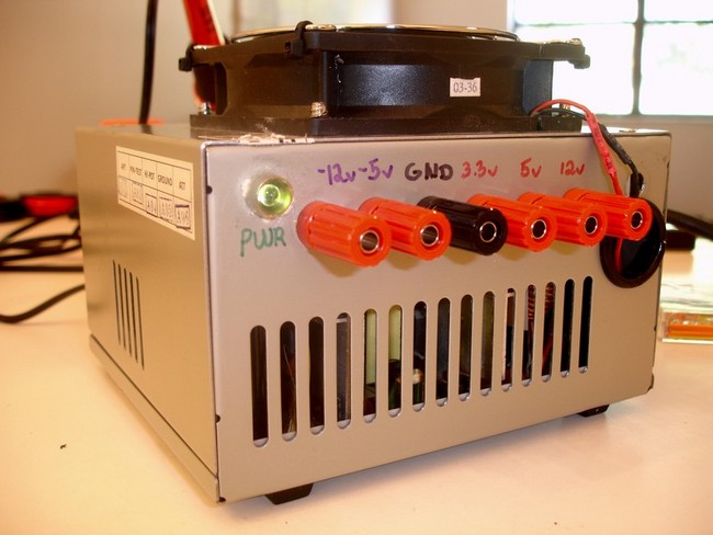
I was tired of wasting batteries while testing my robots and other circuits, and having to dig out voltage regulators every time I needed 5v or 12v for a circuit, so I started thinking of alternatives. I looked into commercial benchtop power supplies like this one, and they're definitely nice, but for 99% of my work, I don't need a fully adjustable voltage and current -- usually I just need one of a few different voltages (3.3v, 5v, 12v, and maybe 9-10v to simulate a 9v battery).
I realized that ATX computer power supplies already put out all of those voltages, and I had one sitting in my closet, so I looked online and sure enough, there's a bunch of guides explaining how to modify an ATX power supply for use as a benchtop power supply. All you need is a power resistor, an LED, and some binding posts. And the cool thing is, these six voltages (-12v, -5v, 0v, 3.3v, 5v, 12v) actually combine to provide a whole lot of different voltages, once you realize that your circuit's 'ground' doesn't necessarily have to be at 0v. I can get 24v (-12v and +12v), 17v (-5v and +12v), 12v (0v and +12v), 10v (-5v and +5v), 8.7v (+3.3v and +12v), 8.3v (-5v and +3.3v), etc.
I won't go through the whole walkthrough and explain every single step, since there's plenty online (I found this one and this one particularly useful), so I'll just post my pictures. IMPORTANT: If you build one, be sure to pay attention to the step where you discharge the power supply's large capacitors by either letting it sit unplugged for several days before opening it, or using a power resistor to short one of the positive lines to ground.
Pretty sizeable current capabilities. Of course, I only used one or two wires per rail, so I wouldn't try to drain this much.
The innards. The upper fan was originally mounted inside the case, but I mounted it on the outside to make room for my wiring.
I would have preferred to solder the wires to the binding posts (because then I could have used more wires per rail), but those binding posts didn't take solder well at all. The thinner wires on the +5v (red) and +3.3v (orange) posts are voltage sense wires -- they have to be connected in order for the power supply to work. The gray wire goes to 5v when the output power is stabilized, so I wired it up to a green LED to act as a power indicator light.
Unneeded wires trimmed away.
ATX power supplies have a 'soft' power function -- the green wire tells the power supply to turn on or off. I shorted it to ground to keep the power supply on as long as the switch on the back is in the On position.
ATX power supplies apparently also need to see a minimum load in order to stay on, so this 10 ohm 10W power resistor takes care of that. Another option would have been to use a 12v light bulb for the power indicator instead of the LED.
The completed power supply.
My workspace (tidied up significantly).


