Okay so my problem was that motors didn't get enough power. I tested this with 6v and it worked.
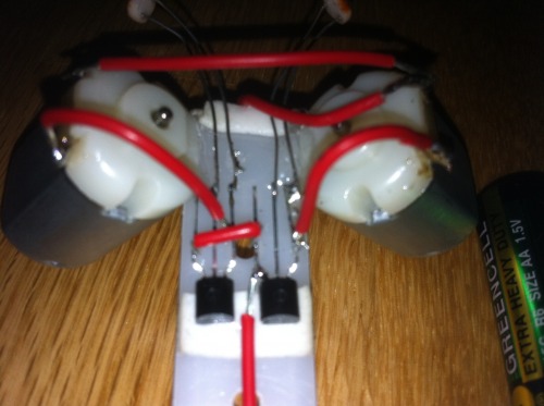
Okay,so here's my third BEAM-robot. But it just don't want to work! I got one picture from very close:
Parts i used:
- some wires - two 2N3904 - two LDRs - two DC motors - AA battery holder
But if you know where i have to connect those wires, or what is the problem, tell me please! I add video when this is fixed. I tested all parts and they work,even transistors! So wiring is the problem?
The LDRs are connected between base and collector now… that isn’t right. they have to be at the middle pin of the transistor and the + which I assume is the most top red wire between the 2 motors in the picture.
* I think the mistake is made by connecting the ldr to the wrong side of the motor.
It was noted his V+ was actually coming out of the bottom wire as seen in the picture. I pointed out that was backwards, so hopefully that is amended as well.
Ah… ok. I didnt see the shoutbox until now. Botfin should change this indeed.
@ Botfin:Ido not want tocomplicate things, if so then ignore this following:
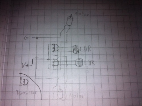
Maybe handy to know that a diode (also the one inside a transistor) in the schematic looks like an arrow, thats the direction the current will flow. in the opposite direction it blocks. And current always flows from positive into negative in a circuit. The protection diode over the motor must always be placed backwards (so it doesn’t passage when motor should be on and fry the transistor!) as seen in the schematic.
I still can remember that I was new into electronics and this kind of basic circuits, and it took a long time, and lots of fried components and hours of thinking and frustration why it doesn’t work as it should. But eventuallyyousucceedand you’re the proud owner of yourrobotthatcompletelydrivesby itself.So justkeep trying.
mogul in your diagram what is the diode doing? cuz it looks like a short to me. + coming out of the motor going back to vcc?
also why is the motor before the transistor? that seems wrong to me. (edit: i looked it up and i guess its just me :S)
heres my attempt:
the motor comes between the emitter and ground, and if needed a diode can be placed between them in series t make sure nothing from the motor gets back into the transistor. also i would put a resistor between LDR/Base and ground. this way the LDR and resistor work as a voltage divider and as long as the values are equal the output in the middle should be half of vcc. if the LDR becomes a lower value the volts in the middle go up.
my theory on what is wrong atm, going off of mogul's drawing:
i think the ldr and motor are working as a sort of quasi voltage divider there, and as soon as the motor gets some action it drops its resistance and leeches the input power away from the LDR, and so the transistor goes low again, the motor is cut off and there you are stuck in a loop.
EDIT: i mistook moguls drawing for representing the original non working circuit :S. it turns out i was wrong and mogul's circuit could work, though there is a chance there might not be enuff current going to the base (i'm not sure why but i ran into that in similar circuits), in which case my solution should work.
As fas as I know to switch a dc motor it’s better to make an emmiter-follower, however I can’t remember exactly why… lets stick us to the original circuit.
about the diode: it will only cause short circuit if placed in the wrong direction.
Imagine: the motor is in fact a coil, and when you put some volt on it it gets a charge. When you turn off the motor the electric charge can come back into the transistor and that can blow up the transistor.
however in this case of a little robot I think Botfin can do it without the diodes. It’s already difficult enough to get this to work for him. He can always add them later.


 and hours of thinking and frustration why it doesn’t work as it should.