multiled-sw-pwm.asm (26292Bytes)
Geir's RGB night light was such an inspiration I just had to make my own. Instead of Picaxes I decided to use ATTiny 2313. At first I tried to program it with C but I ran to some "differences of opinions" with gcc when I tried to assign dedicated registers to variables holding duty cycle values (for speed optimizations). After some struggling I gave up and coded the whole thing in AVR assembly. I was quite surprised how easy it was after all. It took me about one weekend and I got first versions running nicely.
My AVR night light drives 5 RGB leds with software PWM. Using a 8-bit timer, "8-bit duty cycle" ranging from 0 to 255 and 2313's internal 8MHz resonator I got 122Hz PWM. That's enough to get flicker free leds. Leds are driven by two ULN2803 darlington arrays. That's because ATTiny 2313 can only handle 200mA max. I also added a switch so I can change between different modes and a potentiometer to control the speed (of fading or whatever the selected mode does with the potentiometer). Because 2313 doesn't have any ADC's I used 555-timer and one input of 2313 to "read the position" of the potentiometer. I found this page useful: http://home.cogeco.ca/~rpaisley4/LM555.html
And here's some pictures:
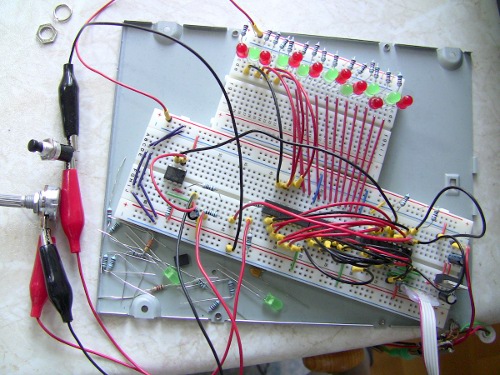
Breadboarding (click for bigger image)
The AVR night light. Connectors below the power switch are ISP (In System Programmer) and power connection.
Electronics, top view
Electronics, bottom view
Last but not least: Thank you Geir for inspiration 
https://www.youtube.com/watch?v=55PkfFj8fxg
Nice work Nuumio! I was
Nice work Nuumio! I was looking to do the same thing with some avr’s that I have as well though I think I’m going to stick with C. I worked on a firefly recently and have been interested in doing the fade…
Thanks. It should be doable
Thanks. It should be doable in C too.
The problem I had with C was something like this: I tried to optimize the speed of TIMER0_OVF_vect ISR to get PWM handling to run as fast as possible (so I could have more free clock cycles to do other stuff). I tried to assign registers to hold duty cycle values like this:
/* Duty cycle values /
register uint8_t dc_00 asm(“r3”);
register uint8_t dc_01 asm(“r4”);
register uint8_t dc_02 asm(“r5”); / And so on… */
It worked just fine otherwise but when I tried to adjust duty cycles it didn’t seem to work. Looking at the generated assembly output revealed that gcc optimized away loops that changed duty cycles (dc_xx). I’m not sure if it’s a bug in gcc or did I just do something terribly wrong. I know it’s not generally a good idea to assign registers like this because it might prevent compiler to do its own optimizations but in this case I needed all the speed I could get to PWM handling.
I cannot remember how many clock cycles the “unoptimized” C version of ISR took to run. Anyway I do have a faint recollection that with 15 channels it too way too many clock cycles. Maybe I’ll check that out later today. Currently my asm version with 15 channels takes 110 (~43%) out of 256 clock cycles (timer0 overflow interval).
Anyway, after looking at the assembly generated from C source long enough I just thought: This assembly code doesn’t look so hard after all. May be I’ll try to learn it and do the whole thing in asm
C will do just fine
I just took a look at my C version of this and if I calculated right I got its ISR running faster than the asm version That’s no surprise after all because this thing was my first asm program so I don’t know all the tricks that gcc does automatically.
The “slowness” I tried to overcome with optimizing thing myself was because of the fact that I tried to do the PWM handling really nice with array containing all port/pin/duty cycle information and looping though that. That approach was way too slow for 15 channels (I might have had a design fault there). But when done in a more “hardcoded” way it’s fast enough. In this case more “hardcoded” means that there’s hardcoded if clause for checking each leds duty cycle value (instead of a nice loop with 1 if-else).
Great to have inspired someone
I must admit that your version looks so much better than mine.
Great work!!
Not better, just different
Thanks!
I wouldn’t say it looks better. It look just different
Anyway, using ping pong balls gave me a bunch of ideas: You can use them as funny looking eyes for robot. Just paint a black spot on the ball for pupil. You could use RGB leds to “indicate the mood” of your bot. Maybe it’s even possible to use little servos to make the eyes move and look around. Or even better: Place a small camera module inside balls to give your robot a stereo vision
On my ’crawler’
On my ’crawler’ https://www.robotshop.com/letsmakerobots/node/17814 I had a plan for using a ping-pong ball as the head and mount the Sharp sensor as eyes. The plan was also having a RGB LED inside the head giving a visual feedback of what the sensor was reading.
Nice
That’s nice
Crawler would have had a bit different “feeling” if you had used that kind of head. Without it it’s more “creepy and mean” and in this case I think it’s better without the “ping-pong-ball-head”. But that’s just me
Found it on Adafruits blog
Found it on Adafruits blog today http://www.adafruit.com/blog/2010/06/24/avr-night-light/


