

Examples
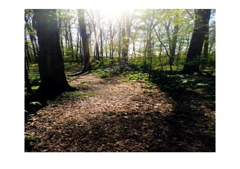
Original

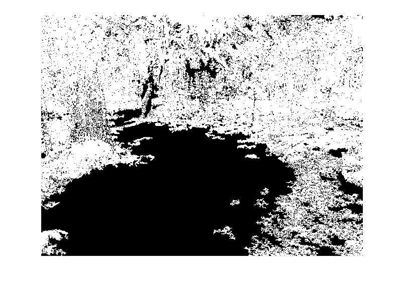
Processed (White is impassable terrain)
Obstacle Detection:
based on and taken from:
Ulrich, I. 2000. Appearance-Based Obstacle Detection with Monocular Color Vision. In Proceedings of the AAAI National Conference on Artificial Intelligence.
The basic algorithm utilizes histograms and a "safe" area to detect impassable terrain in the environment. It is assumed the area directly in front of the robot is clear of obstacles, and can be used as a reference. A histogram of this safe region is generated. The more advance alogrithm stores histograms from past travel, and uses those as known "safe areas". Then the image is scanned pixel by pixel and the value of each pixel is compared its bin in the histogram of the safe region. If the number of pixels in the bin is below some threshold, that pixel is classified as belonging to an obstacle. The HSV color space is used instead of the RGB color space because it is more resistant to changes in lighting.
Implementation:
Implementation so far can be found here: https://github.com/williamg42/AGV-IV/tree/master/Autonomous/Autonomous_Obstacle_Avoidance
The current code is only the segmentation algorithm, which applies the basic algorithm described above. A more advance algorithm is currently under development.
Obstacle Avoidance:
based on and taken from:
Horswill, I. 1994. Visual Collision Avoidance by Segmentation. In Proceedings of the IEEE/RSJ International Conference on Intelligent Robots and Systems, 902-909.
Assume there robot has a forward-looking camera. Let I(t) be the image at time t and let D(.) be the obstacle detection algorithm described above. We define the bottom projection ("bprojection") of the binary image J to be a vector b(J), indexed by x (horizontal) coordinate, whose x'th element is the height of the lowest marked pixel in the x'th column of J:
bx(J) = min{ y: J(x,y) = 1}
It will be shown below that under the right conditions, b(D(I)) is a radial depth map: a mapping from direction to the amount of freespace in that direction. Given the radial depth map b(D(I(t))), we define the left, right, and center freespaces to be the distances to the closest objects to the left, right and center:

Where xc is the x coordinate of the center column of the image, and w is a width parameter.
Now if we assume the robot is a true holonomic drive (which it is not, but we can "convert" and angular and translation velocities to left and right wheel velocities fairly easily. This should allow the robot to avoid hitting something but will not maintain its previous direction vector, which is fine for now)
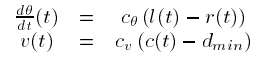
Where dTheta/dt is the angular velocity, v(t) is the translational velocity, and dmin is the closest a robot should ever come to an obstacle, and c_theta and c_v are user defined gains. There will also be velocity cap on the equations to limit the robots maximum speed, which are not mentioned in the equations for simplicity.
10/20/2015 Update:
Significant steps have been made!
To begin with, the Beaglebone Black is non-longer controlling the AGC platform. For some reason the PRU outputs are no longer being routed the physical pins, and as a result the PWM signals are not being sent to the motor controllers. Dmesg tells me that more than one PRU is exported, and some other errors. I believe the issue has to do with how the PRU's are handled and a combination of updates to the default kernel that rolled in the patches need to get a PRU to work and potentially a problem with my device tree. The other big issue is my custom device tree is not loading at boot, and I have no idea why it is not. Combined with the poor performance with regards to JPEG decompression, the Beaglebone Black is being replaced with an Odroid UX4.
With the goal of running everything on the Odroid UX4, I've began work on both installing OpenCV 3.0 with OpenCL, OpenGL, Jpeg-turbo, and Intel Thread Building Blocks on an Odroid C1 and Odroid UX4. Currently I have OpenCV 3.0 running on an Odroid C1, as you can see in the first video. I am limiting the video generation to 5 fps, but when not creating a .avi file the framerate is closer to 8 to 11 fps.
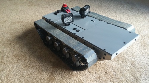
I've also worked on the design of the top of the robot. It's design to contain the USB, Ethernet, lights, and other wired devices while still allowing the top to be removed so I can work on the inside without a huge hassle. I also designed a recharging port to recharge the internal AGM lead-acid battery. It's a waterproof cigarette lighter socket for a motorcycle.
As soon as the Odroid UX4 arrives in the mail, I will begin intergrating it into the IP66 enclosures. However since the Odroid UX4 does not have PWM built it, and since the inability to put watchdog timers, or other failsafes would be bad. Therefore I will be using some microcontroller to create the PWM signals, as well as other nice safety features. This microcontroller will be talking to the Odroid UX4 over UART.
That's it for now!
5/9/2015 Update:
Been a while! Sorry, work has been really crazy lately (I've learned to hate USB). Not too much progress has been made, mainly on the software side. I've ordered some IP66+ housings and connectors so I can begin ruggedizing the electronics inside the chassis. I've also gotten and optimized OpenCV with libjpeg-turbo install, and the frame rate is still less than impressive. I think I many change the overall design, and have an Odroid C1 I have sitting about do the image processing and other CPU intensive applications while the Beaglebone Black is the actual interface to the rest of the robot.
I've also made a video showing the difference the suspension system makes. (It was originally for a design presentation, so sorry its a bit cheesy.) It's above and a link is also here:
https://www.youtube.com/watch?v=LrrsIusZDR0
4/7/2015 Update:
Progress has been made! Over the weekend, I cut the axles on the mini-cim motors so that they could be used with my current gear boxes and mounted them in the chasis. It was a really tight fit, and the only way to get the gear boxes back in was to remove the front of the chasis.
But they fit really well and are securely bolted onto the frame. By replacing the motors, the maximum torque went from 188 lbs-in to 694 lbs-in. The top speed did drop from 6 mph to 3 mph, but honestly it'll make controlling the system a lot easier.
I also did some more work on the top of the robot. I added the kill/battery disconnect switch, an external soft-power off button, a wifi antenna, and a waterproof USB mini extension cable. Its not water resistant yet, but ideally I would want to make sure the system is at least IP - 5 4. So I still need to seal the holes and put o-rings around bolts, but it is good enough for the moment. Next step is to take it outside and see how much of an improvement the new motors are. Hopefully I will have a new video up soon!
I also need to redo the rubber strips on the treads, make sure they are all the same length and uniform.
Original:
Hello everyone!
So it has been a year since I have really posted anything, and I am happy to say I have finally got to the point where all of the core features work and I am ready to show what I have been working on. So a little back story first.
The second video embedded was create by DARPA to showcase what they called the Advanced Suspension System for Improved Mobility being developed under the Maximum Mobility and Manipulation (M3) program. It shows how much of a difference a functional suspension system can make in terms of driving abilities and ride stability for an outdoor vehicle. I decided to try and create my own version of it. The progress I made on that was mainly documented on my previous post as I build a prototype out of plastic (acrylic to be exact). It suffered from numerous problems because it was made from acrylic. However after several members of this community mention trying to machine the parts out of metal, I looked into it. After a year of work, here is what has come out.
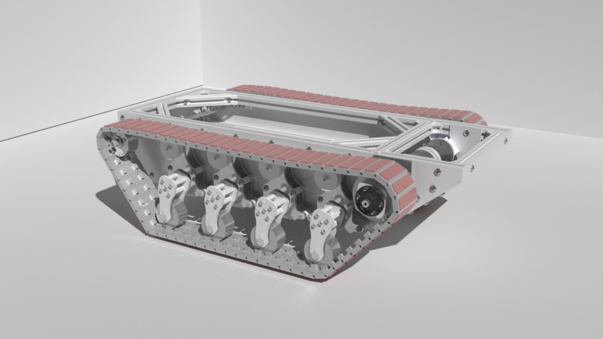
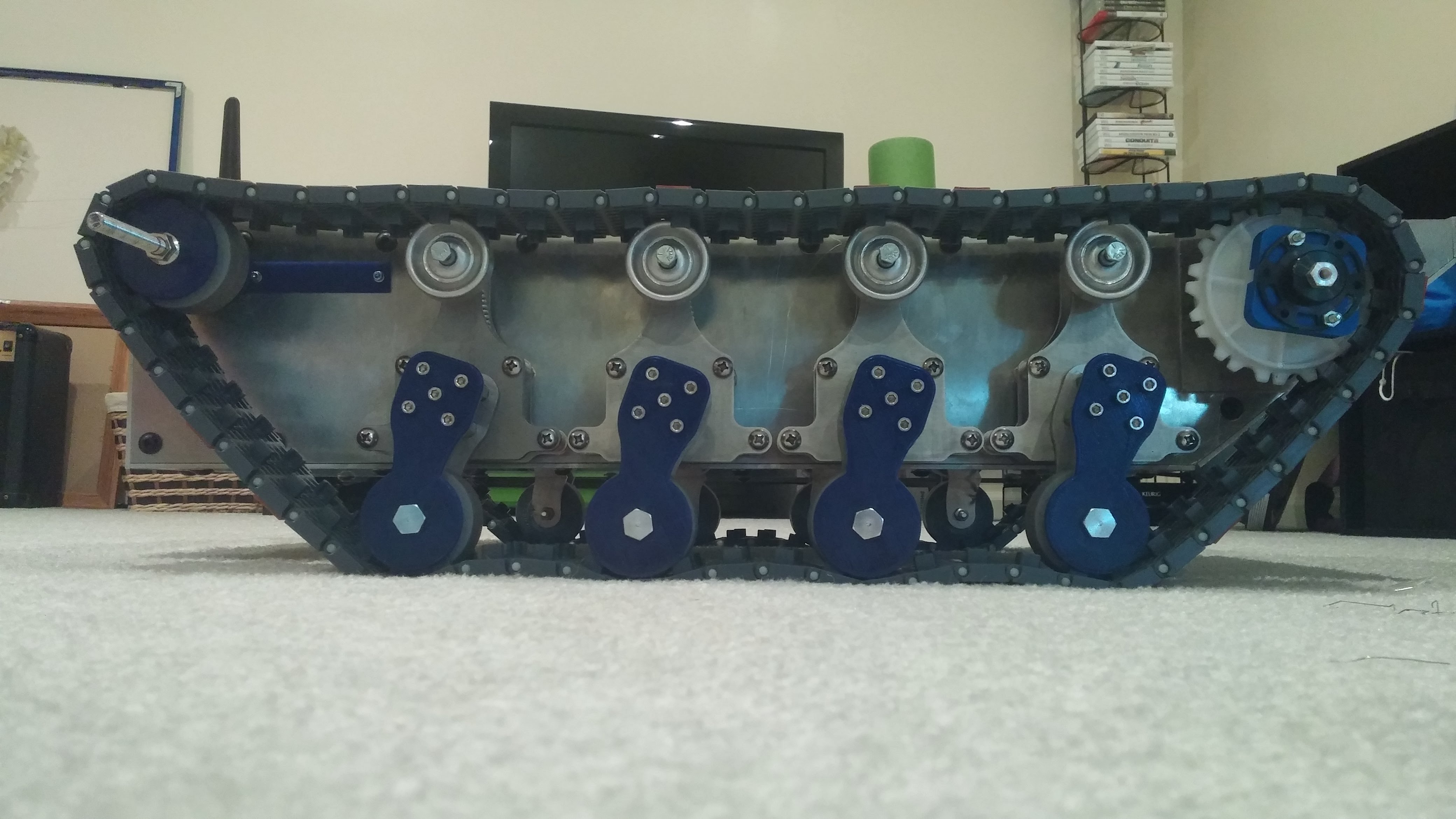
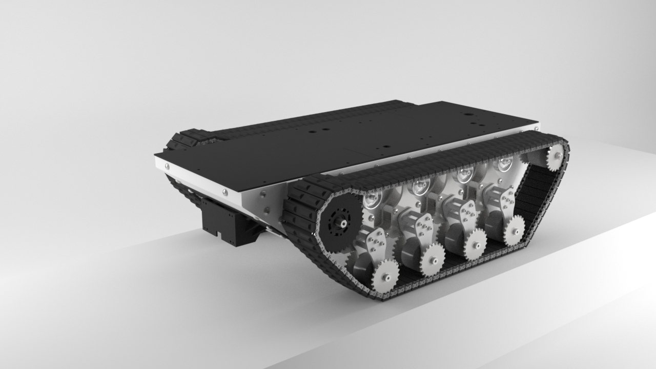
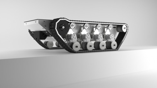
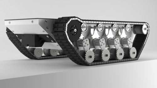
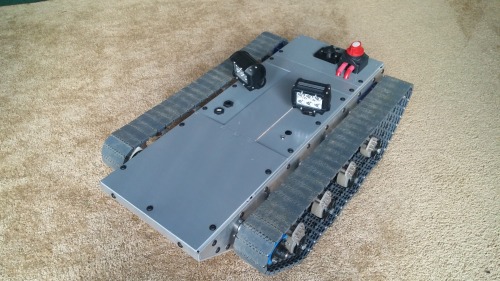
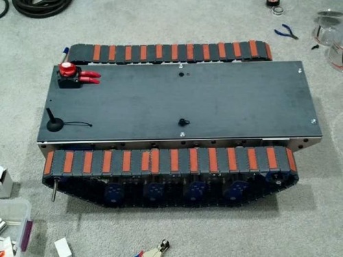
This is the improved suspension system. The third video is an old simulation, but the new system works the same way. It also features PETG tread retainers which help keep the track aligned.
The track itself is made from delrin and comes from a company called Intralox. They are actually industrial conveyor belts. The biggest issue with them is on smooth surface, the delrin has very little traction because it is so slick. To help I've attached rubber strips to some of the track links to improve traction.
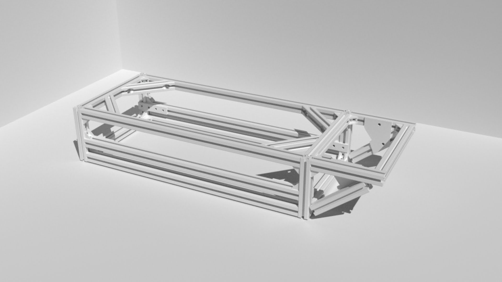
I don't have a lot of photo's from the assembly process but I do have quite a few CAD renderings. It took quite a bit of tweaking to get all of the pieces to work the way they should.
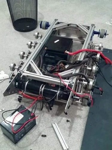
Mechanical:
The frame is made out of extrude aluminium beams which are bolted together. Side panels and suspension pieces bolt into this frame. The overall idea is if design requirements change, the frame can easily be changed and only a few pieces need to be redesigned and replaced. The side panels are made from 6061 Aluminium, while the suspension system is made from stainless steel. It was also designed in Autodesk Inventor and fabricated on a water-jet cutter.
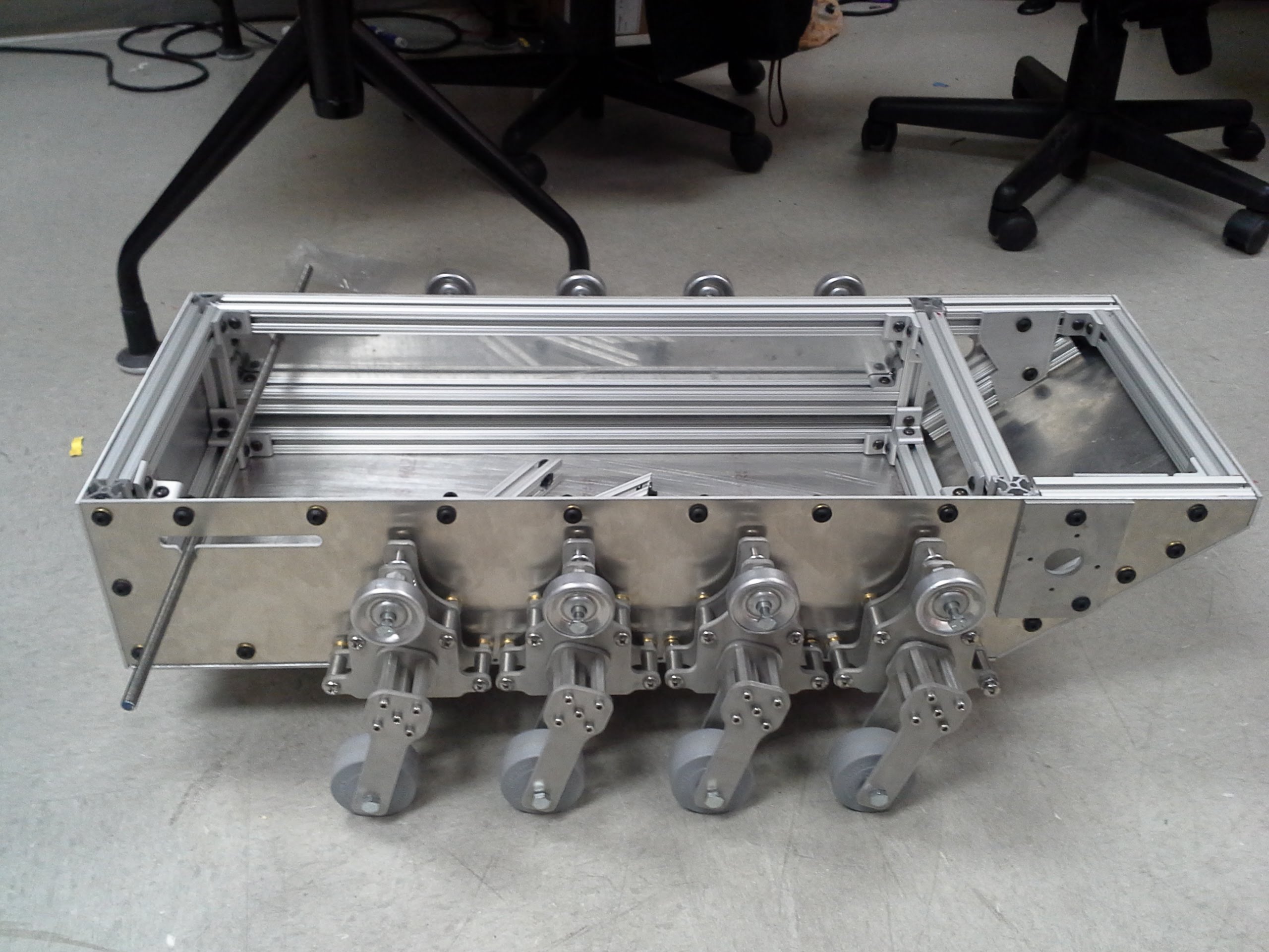
Drive Train:
Currently the drive train consists of two versaplanetary gearboxes, which are very nice metal gearboxes created by VEX robotics for FIRST robotics competitions. Currently the gear ratio is set to 1:28 with two BAG motors. Now, due to the increasing weight of the system, the BAG motors are being replaced with mini-CIMs (hopefully this weekend) which should raise the maximum torque from 98 lb-in per motor to 347 lb-in per motor, while dropping the top speed from 6 mph to around 3 mph.The current power source is a 26 AH lead acid battery.
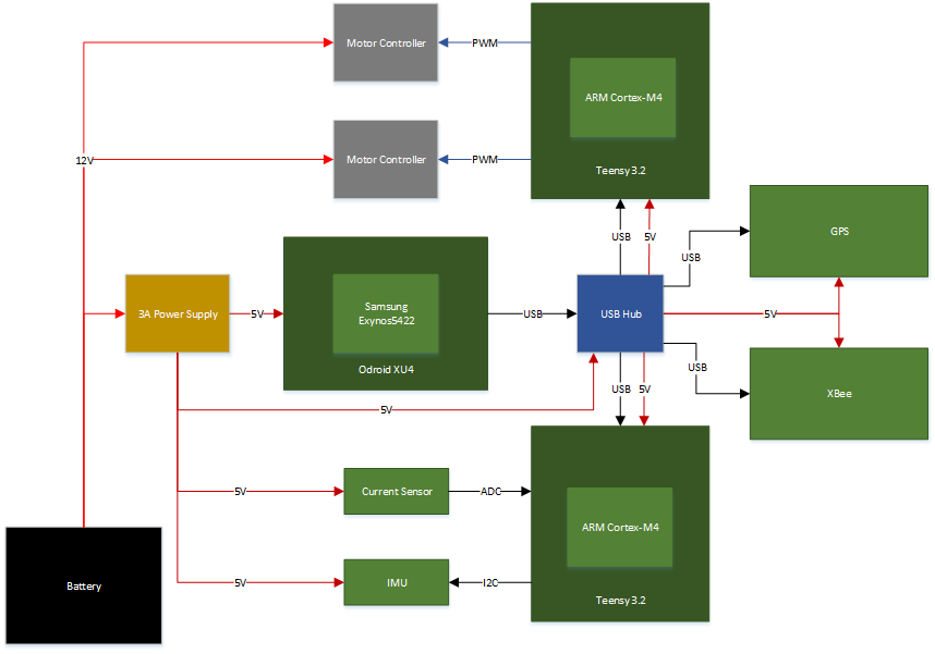
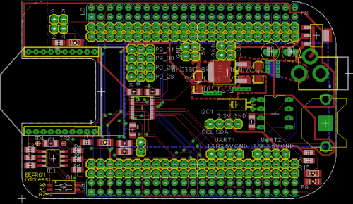
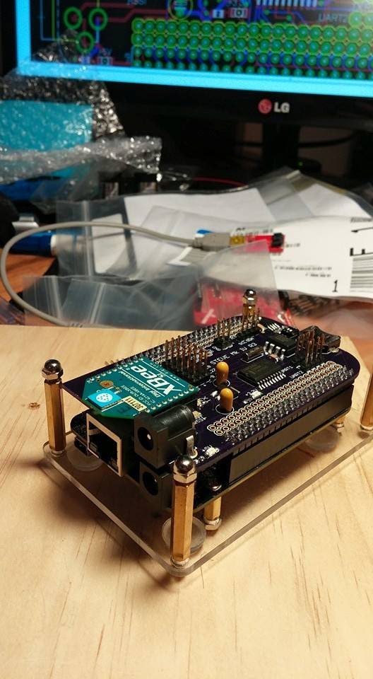
Electronics:
Since the plan is to make this platform have both autonomous and semi-autonomous capabilities, I decided to use a Beaglebone Black as the primary control unit. To that end I used eagle to design a custom cape which contains a real-time clock, 3.3V power supply, logic level conversion, EEPROM for automatic device-tree loading, header pins to connect an xbee, and breakouts for any comms interfaces and GPIOs I might use. The system does have an external 5 volt buck converter to power both the Beaglebone Black and its cape as well as the USB hub.
The motor controllers are the old jaguars also designed for FIRST robotics teams. Now they are only rated for 40 amps continously, and may need to be replaced after I replace the BAG motors with Mini-CIMs.
Sensors:
Right now I have bought several sensors but have not mounted or done software for them yet. The plan is to use the combination of a LIDAR Lite and USB webcam to emulate what several teams did for the DARPA Grand Challenge in 2005. The camera will be used to look for long-distance obstacles and create a histogram history of what the system has been driving on. If it sees something that does not match this history, the platform will slow down. The LIDAR Lite unit will also be actively scanning an 180 degree arc in front of the robot for obstacles. Hopefully together the system can create a "map" which will allow the platform to avoid hitting anything that should not be hit (such as people ;) ) and plan paths around terrain it cannot drive over. There is also plans to add an IMU and CMUCam V5 for additional functionality, like recognizing its charging station, etc. Here is an example of what the camera algorithm spits out so far (I am using OpenCV 2.11)
Software:
Since the Beaglebone Black is running a distro of Linux, its ability to do real-time operations is not great. However the Beaglebone Black does have two 32-bit micro-controllers (called PRU or peripheral realtime units) built in. They can be programmed from the user space and used to perform real-time operations, like generating precision square waves. http://www.embedded-things.com/bbb/wireless-servo-control-part-3-pwm-servo-control-with-the-bbb-pru/ does a great job explain how that is done and their code is very nice, it worked with minimal modification for my application. The rest of my code is on my github (or will be soon): https://github.com/williamg42
Right now all it is just a simple serial server that reads in data from the Xbee, runs the joystick data through a simple moving average filter, and maps the values to a PWM period.
Thanks for reading and I will be sure to keep this page up to date! (Forcing myself to keep better documentation :) )
More information:
https://sites.google.com/a/vt.edu/amp_lab/projects/autonomous-ground-vehicle-mk-iv
Outdoor autonomous rover
This is a companion discussion topic for the original entry at https://community.robotshop.com/robots/show/autonomous-ground-vehicle-mk-iv-12-15-2015-update

