Me and my wife just bought an old house. Inside the house is an old oil heating system that after this winter gets exchanged to a newer system.
Currently this heater gives me work: every three days I have to empty a little tank that gets filled up with condensed water from the chimney. Enough motivation to automate this task with a pump.
There are several pump systems out there that could do the job. But they cost a bit and I need it now.
So here is how I built this Automatic Condensate Removal Pump.
Why does Water Condensate? Here Some Physics.
Inside the chimney the warm exhaust air from the heater meets the cold air from the outside. This meeting point is the dew point where the air gets cooled down and its relative humidity exeeds 100% so water condensates out of the warm air.
Having mathematics for the dew-point is important for civil-engineers but also for pilots and
other professions like heating system engineers. Pilots calculate the lower base
of clouds. Civil engineers the point where i.e. inside a wall the water condenses...
and try to avoid that. Heating system engineers the point inside their pipe-systems
where water must be drained. Then they use something like this little pump here to
get rid of the condensed water.
The Making
Here some impressions from the making.
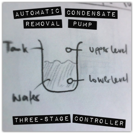
From this schema I got the details on the sensor.
The new sensor got tested... and it worked fine.
Then this pump got embedded into the tank...
...and the sensors too.
As usual next to me is one son. He interprets my drawing and makes his own colored version
of the system diagram.
The electronics using resistors and capacitors. All put into this little plastic case.
Fitted fine.
Some indicators to let the user know what is going on.
Green ON light and RED pump light indicated normal idle mode.
Green ON light and BLUE pump light indicates pumping. BLUE until done. Then RED again.
The software consists of a controller that is either IDLE or PUMPING. Depending
on the input events FULL or EMPTY. The controller emits a START event that
sets the pump process to ON. It also emits the STOP event that sets the pump
process to OFF.
Each sensor is modeled too. The upper level sensor emits WATER_DETECTED
if it goes HIGH. It's HIGH if the voltage detected by the sensor drops below a
defined value.
The Pump Controller has input channels and output channels. Input events come
in via input channel. Out-events go out via output channels.
Inside the cluster the events go directly as pulses from one process to the other.
So that in the end this little device does exactly what is should.
This pump runs now for a couple months until the new heating system is implemented.
After that the device gets disassembled... and reused for other future projects.
This is it. Done done. Happy pumping.
Further Readings
NEW V3 Arduino Motor controller Shield L298N 2 motors
"The Arduino Motor controller Shield is based on L298N chipset, which is a high voltage (46V max), high current (2A per phrase) dual full-bridge driver, that can control two motors simultaneously."
Dog needs water alarm
The sensor is made by putting two bolts through the bottom of the bowl and simply test if there is electric conductivity between them.
Appendix A: Motor Shield Settings
Motor voltage is 12V-16V
This case can only be extended through the motor drive board and the VEX GND terminals to the two power supply to the motor, motor-driven expansion of the board at this time 5V logic voltage converter circuit can work properly. In this case the motor-driven expansion board is set to:
- VLO:ON,Board need to motor drive circuit is extended
- VLC:OFF,Not with Arduino's 5V pin connection, security isolation
- VM:VEX, Extended through the motor drive board VEX / GND terminal for the motor to provide drive voltage
These settings because VLC has not Arduino's 5V pin expansion board with the motor connected 5V logic voltage, so we need any additional power supply for the Arduino (via USB cable or external power supply), mainly for security isolation Consideration, especially in the VEX relatively high voltage on the case.Used Pins: 8, 9, 10, 11, 12, 13.
Motor A: 10, 12, 13. Motor B: 8, 9, 11. 9 and 10 are the speed pins.
https://www.youtube.com/watch?v=5z7Jl31BHzU


