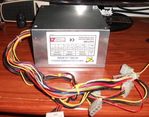
This project involves adaptation an ATX power supply for computer, often found in junk or very cheap cost, but offering an excellent power supply with standard voltages (+5VDC, +12VDC, +3.3VDC, -12VDC and -5VDC) with high current capability. In this case, we will have maximum capacity 28A for +3.3V, 50A for +5V, 18A for +12V and 1A for negative tensions.
There are many tutorials for adapt ATX power supply, but I decided to share my experience for those who may be interested. I hope to help anyone looking to do this type of project.
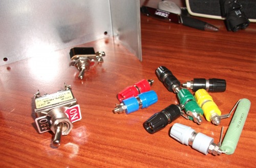
The COMPONENTS used in my project were:
1. ATX Power Supply used (working obviously);
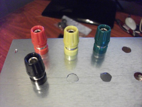
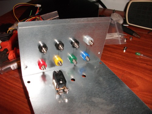
2. Banana Jack (8 units, different colors). I used 3 black jacks (for ground) and others colorful, a different color for each voltage: +5VDC/Red, +12VDC/Yelllow, +3.3VDC/Green,-5VDC/Gray and -12VDC/Blue;
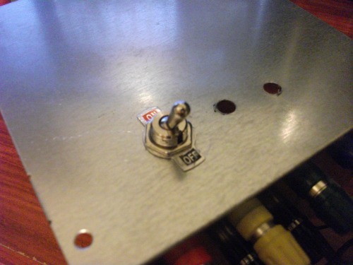
3. ON/OFF Switch;
4. LEDs: one red and one green, one for identification "standby" (green) and other for "power on" (red) status;
5. Resistor 330 ohm, 0.33W (two, for LEDs);
6. Resistor 10 ohm, 20W (used in +5VDC output);
TOOLS: Besides the normal tools will be needed a drill to make the holes in the cabinet of the power supply to installation of the components.
WORKING:
Well, before you start it is important to know a little about ATX power supply. For this, I recommend reading the document (in link), "ATX12V - Power Supply Design Guide", especially page 34, figure 10, showing pinning of various connectors from the power supply.
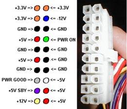
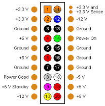
Of many connectors, it is important to know that the most important connector is the larger connector, "Main Power Connetor" of 20 pins (see drawing above). This connector contains all the source voltages and also some control signals, which are:
Pin 8 / PWR_OK signal: It is a “power good” signal. Indicate that the +12VDC, +5VDC, and +3.3VDC outputs are OK to guarantee continuous power operation within specification. Gray cable (*).
Pin 9 / +5VSB signal: Output, +5VDC in standby, maintains +5V output even with the power off. This line is used in computers, to power some circuits during power off operation. I will use this signal to feed my green LED that shows when my source is in the making, even in power off. Purple cable (*).
Pin 14 / PS_ON: Input, this is an active-low, TTL-compatible signal that allows a motherboard to remotely control the power supply in conjunction with features such as soft power on/off. This is the sign that we will use to connect and disconnect the power supply. As described, it should be active-low. This signal is connected in the on/off switch and the other point of the switch, in the ground signal. Green cable (*).
The other wires on the Main Power Connector are the tensions that we will provide: +3.3VDC (orange cables), +5VDC (red cables), +12VDC (yellow cables), -5VDC (white cable), -12VDC (blue cable). (*)
(*) WARNING: The wire colors may change according the power supply manufacturer. Most use standard colors that will speak, but pay close attention and not be guided only by the colors that I mention here.
Other important information on adaptation an ATX power supply is the need to install a load on the +5VDC output as without it, the systems for protection of power supply does not allow her to power on. This is the load resistor 10 ohms/20W (or 10W) which we put in the output of +5VDC.
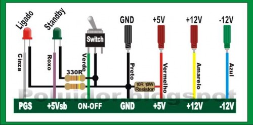
(sorry to be in portuguese this above picture)
MOUNTING IT:
STEP 1: Planning and making holes in the power supply cover for installation of the jacks to the output voltage, on/off switch and status LEDs.
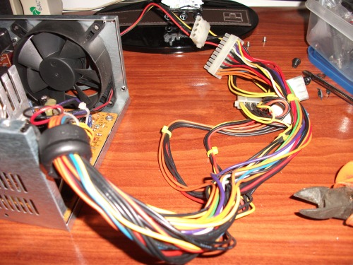
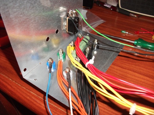
STEP 2: Knowing and identifying the cables from the power supply.
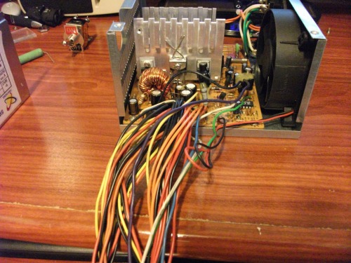
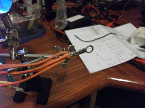
STEP 3: Gathering the right cables and making connectors.
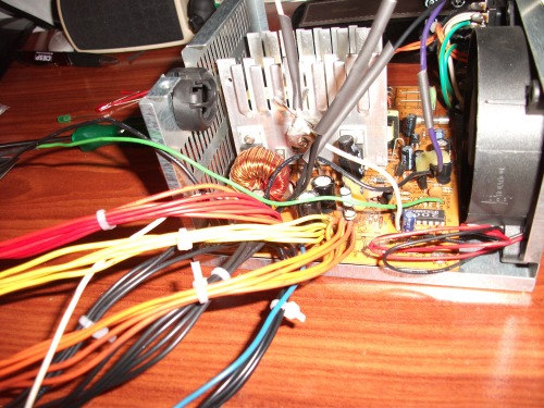
I decided to use all the cables and join them for security provide high output current capability. I joined the black cables (GND) in 3 parts to divide between 3 jack connectors.
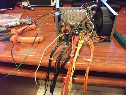
STEP 4: Plugging cables into connectors jack and connect the wires from the on/off switch.
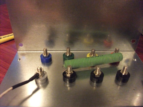
Look at the detail of the load resistor of 10 ohm/20W which I put in +5VDC, very close to the connector jack, but inside the power supply. It is important to generate a load on +5VDC because without it the power supply will not turn on.
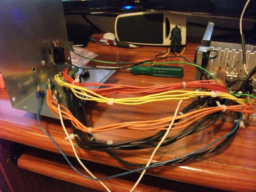
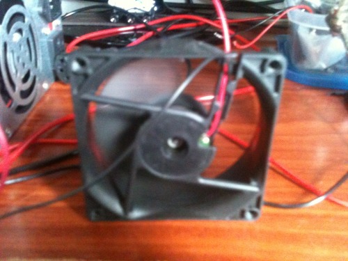
The long cables as pictured above is very good for maintenance, but too bad when you close the power supply. I had some problems with the length of the cables depending on the lock, is generated noise because to lean in internal fan. I'll leave it this way but I recommend leaving the cables a bit smaller. Will help in time to close your power supply!
STEP 5: Powering LEDs and setting in the power supply cover.
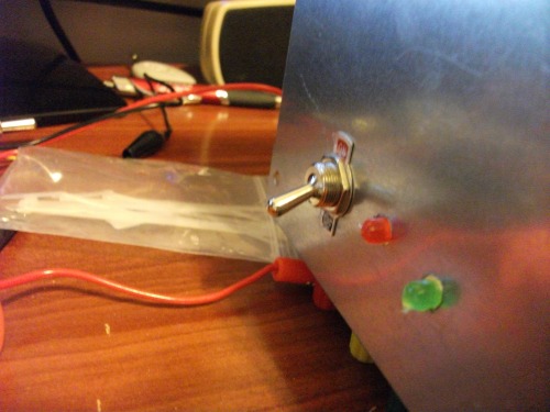
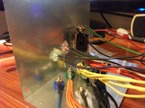
Well, I had to use hot glue to attach the LEDs because I had no support leds. But in the end it was not so bad either. I think...
FINISH!
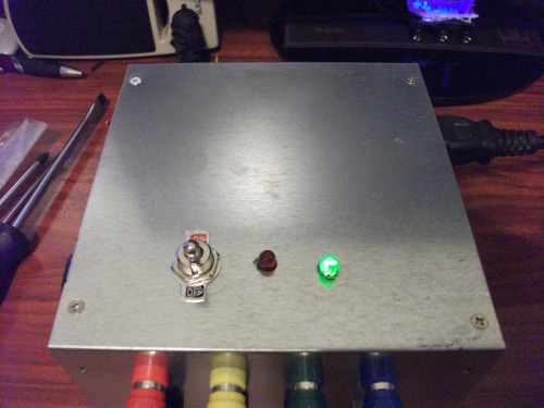
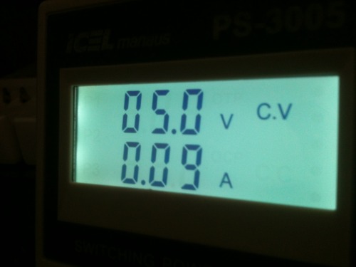
In standby (green LED on), its OK!
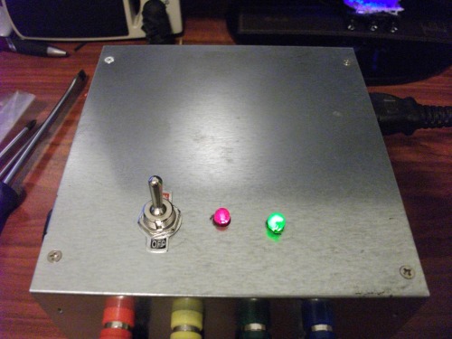
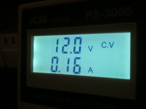
In Power On, red LED on and outputs OK!
 (ok, i am just kidding).