Attiny85 h-bridge ldr robot

I have an idea for making an simple robot. Maybe solar powered... doesnt have to be...

I have an ATTiny85, an h-bridge from an arduino motorshield (L293D, I think) and some LDR sensors and some 3V-6V motors.

My question is, can I somehow put them all together to make a simple robot? If so, do I need anything else, besides simple resistors and capacitors? Or am I missing something?

Update 3-25-2012: So I used this simple code to program the ATtiny using the Arduino as ISP


void setup() {                

  // initialize the digital pin as an output.

  // Pin 13 has an LED connected on most Arduino boards:

  pinMode(0, OUTPUT);

  pinMode(1, OUTPUT);  

}


void loop() {

   digitalWrite(0, HIGH);   // set the LED on

  delay(1000);              // wait for a second

  digitalWrite(0, LOW);    // set the LED off

  delay(1000);              // wait for a second

  digitalWrite(1, HIGH);   // set the LED on

  delay(1000);              // wait for a second

  digitalWrite(1, LOW);   // set the LED on

  delay(1000);              // wait for a second

}


Here is a picture of my circuit

IMG_1256.jpg


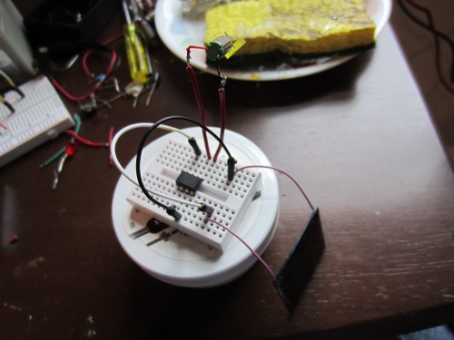
Check out the video! I got the motor to turn both directions. Forward and reverse!


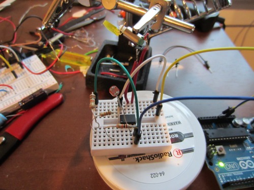
Update 2 - 3-25-2012 : I added a LDR sensor to the circuit and updated the code to turn the motor forward if the analog reads less than 500 and opposite if it read more than 500.

int photocellPin = 2;     // the cell and 10K pulldown are connected to a0
int photocellReading;     // the analog reading from the sensor divider

void setup() {                

  pinMode(0, OUTPUT);

  pinMode(1, OUTPUT);  

  digitalWrite(0, LOW);

  digitalWrite(1, LOW);

}

void loop() {

  photocellReading = analogRead(photocellPin);   

 if (photocellReading < 500){

     digitalWrite(0, HIGH);    

     digitalWrite(1, LOW);  

 } 

   if (photocellReading > 500) {

     digitalWrite(0, LOW);    

     digitalWrite(1, HIGH);   

   }

  delay(150);       

} 

IMG_1265.jpg


https://www.youtube.com/watch?v=1BYs6fu32_c

well you only have 5 i/o

well you only have 5 i/o pins on the attiny85, so if you want reverse you will have to get creative with the sensor input to get it to work on 1 i/o.

but yeah you can do it.


I got the same idea in mind

I got the same idea in mind and it should work with only 1 sensor input. 

you need 4 outputs for the motors (forward /reverse) if you want to go in both directions.  the remaining input can be used for the LDR. just try it with a permanent lit up LED and use an analog input for the LDR to measure the value and calculate the distance.

If you tie the Enable pins

If you tie the Enable pins to Vcc, then use a transistor as an inverter on one of the direction pins, you can control the motors with only one microcontroller pin per motor, thus freeing 2 pins for sensor use. The motors will go one way for PWM=0, stop for PWM=127 and go the other way for PWM=255.

thats what I am thinking

thats what I am thinking too. Use some type of inverting signal for the h-bridge. It sounds good in theory, lets see if I can get it to work in real life.

What about using the motor
What about using the motor directly to the ATTiny? As in connecting it to two outputs? Will that work if the motor is very tiny like the pager motor? Just give a 1,0 or 0,1 to turn the motor both ways.

You may want one other IC.

A voltage regulator would be a good addition to your chips and pin headers might also be welcome. You could save yourself the motor driver and just use converted servos and save yourself a couple pins at the same time or add a couple not gates to your h-bridge inputs to slim your pin usage to a single pin. There is also a much more complicated circuit that will allow you to use a single pin, but, by complicated I mean it requires a number of discrete components to complete.

LVDO (low voltage drop out) regulator https://www.robotshop.com/letsmakerobots/node/8083

complicated single pin per motor circuit https://www.robotshop.com/letsmakerobots/node/17370

how about tying the reverse

how about tying the reverse lines together on 1 i/o pin?


I am half way done with mine

I am half way done with mine (https://www.robotshop.com/letsmakerobots/node/31848) I am using 2 motors forard/reverse, so I need 4 pins and got still one pin left for the sensor. I was thinking to use a bright LED and a LDR combination to measure the changing of light compared to the ambient light. 

That looks really good. I
That looks really good. I might have to use your code for this one as you know I am not good at coding. I am still using your code for the chopstick walker :slight_smile:

Cool, I hope the code works

Cool, I hope the code works for you as I have my own way to program certain things :wink:

Well, when I am done I will attach the code to my project, feel free to use it. Right now it’s just a pattern of pre-programmed moved to see if the whole motor bridge works.


what surprises me is that no

what surprises me is that no one has done something like this before. Or maybe I didnt look hard enough. I havent seen anyone use a ATtiny85 as a brain for a bug/bot. I wonder why?.. but I am sure people can prove me wrong.

There are some here using

There are some here using ATTiny but you really have to search for. I also got a hard time to find smething what helped me to get  a start with those little bugs :wink: