Update 1/3/24
Code and Videos added....Video on the headlights test and automatic obstacle avoidance test.
Videos here : http://youtu.be/SZA4--jDd7U and http://youtu.be/XaVSwtYGNgs (Embed not working for some reason.)
Cheers!
Update 27/2/14
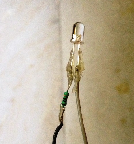
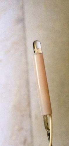
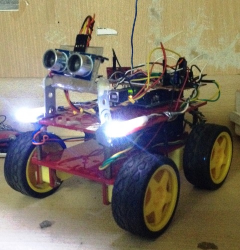
Small update on the rover....added headlights (activated wirelessly through the remote) and the HCSR04.Also made good progress on the automatic braking code.
Update 22/2/14
Hello fellow LMR folks...in this update I decided to scrap the whole 3 function rover idea(hence the name change) as I wasnt getting time to work on the code (still need to learn how to ue interrupts).The plan as of now is to integrate automatic obstacle avoidance with the wireless control using the HC SR04 ultrasonic sensor so that the robot automatically brakes if collision is imminent and overrides the controller in order to avoid any obstacle. Since I had a electronics project exhibition in college I decided to submit the rover for it.I made modifications to the chassis and added a mobile phone mount in order to get FPV on the rover.The mobile phone transmitted live video feed from the rover to my computer using skype (kinda like a mini telepresence robot).I've attached new pics of the rover with the mobile phone mount and the controller board. I have begun working on the automatic obstacle avoidance phase of the rover right now and it should be ready soon (probably the next update).
This rover is an upgrade to the previous one I had built. I have soldered a new and better remote instead of going with a breadboard version. The use of a joystick for controlling the rover is much more comfy and easier compared to the four pushbuttons used in the previous remote.There is one Arduino on the rover connected to the Rx and another Arduino clone board on the remote connected to the Tx. I have used 433MHz RF modules to control the rover wirelessly. Right now I have completed the basic controlling of the rover via the joystick.
There is still alot of work left in terms of coding the rover....I still have to incorporate the line following bit,obstacle avoiding bit and being able to switch between these modes into one code. :p
The 3 pushbuttons on the controller are for switching between functions or modes(for eg :- from RC to Obstacle avoidance mode or line follower mode).
For motor control I have soldered a motor shield on to a pcb using the schematics of the adafruit shield.So far only the HC SR04 module and motor shield are wired up.....still have to solder the IR leds for the line following module.
The only real problem I am facing here are the batteries which dont seem to last very long (already used 2 packs i.e. 8 AA batteries). They are normal,non-rechargeable AA batteries. I plan on buying rechargeable ones but not sure which ones to buy...Any help on this would be welcome :)
I hope to have an update on the build of the rover soon....atleast one sensor up and working. Stay tuned!
RC,Obstacle Avoidance,Line Following
- Actuators / output devices: Dc geared motors, micro servo
- Control method: autonomous, RF
- CPU: arduino uno
- Operating system: Arduino
- Power source: 12v 8xAA battery pack for rover, 9v for remote
- Programming language: Arduino
- Sensors / input devices: RF, IR sensors, HC SR04
- Target environment: indoor, outdoor, Mars
This is a companion discussion topic for the original entry at https://community.robotshop.com/robots/show/arduino-rover-final-name-tbd


