Arduino Object Avoidance with PING and Hacked RC Car

Finished Bot Here: https://www.robotshop.com/letsmakerobots/node/26101

Before I begin I am a Senior Electrical Engineer student in college. This is a project im working on for my design class. I am very new to arduino and its language. Having said that here we go:

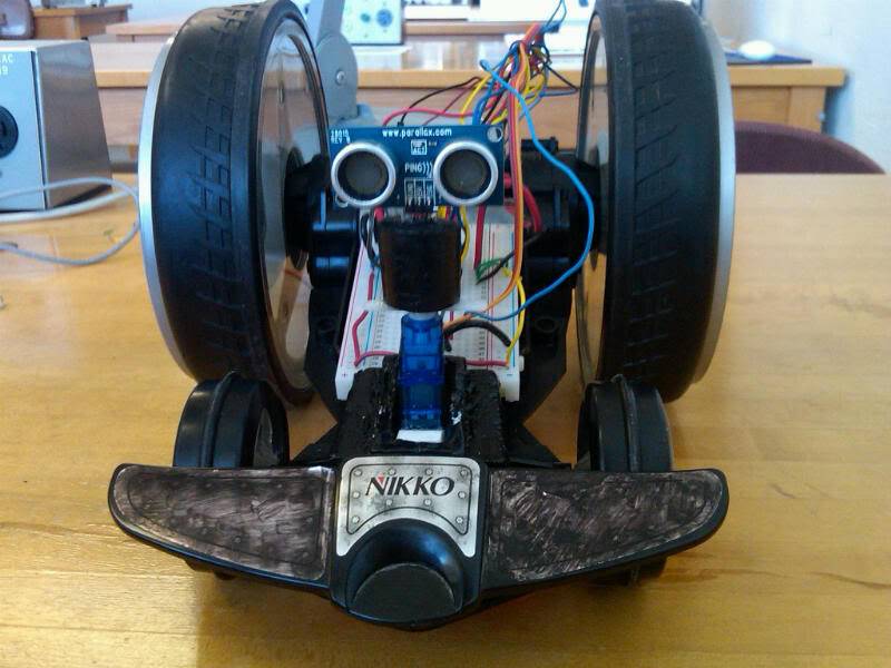
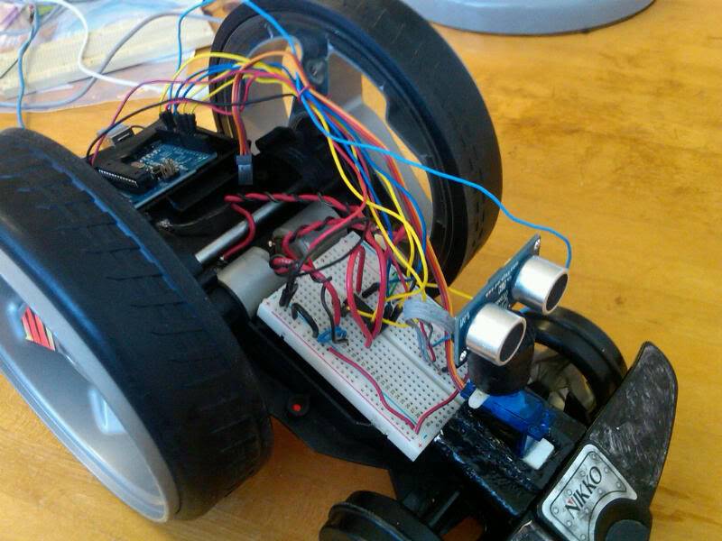
Working on an object avoiding vehicle using Arduino and Ping ultrasound sensor. I hacked an old rc car. Basically removed all the guts and replaced it with a breadboard and the arduino. I am still using the 9V rechargeable battery pack that came with the car to power the 2 motors through an L293D chip and a regular 9v battery to power the arduino. When I turn on the robot it runs well and responds while im holding it in the air so the code seems to be working. But then things go bad. Here are the issues i've come across so far.

After a while it begins to slow down and stop as you can see in the video. Battery is charged

When changing directions it badly stutters. will post another video soon showing this.

Not enough torque to run on carpet. Runs on tile but slows to a stop when changing directions.

When I grab one wheel to stop it while its running the other slows and eventually stops. Not too much of an issue there but just wondering why it happens since they are running independantly? gueesing it has to do with the overheating of the L293D.

I left the original two capacitors going across the motors attached, tried removing them and had same issue so I put them back. Also the L293D (can handle 0.6 amps) chip gets VERY hot while its running and starts to smell like its burning. I ordered a chip called  ‘SN754410‘ from Texas Instruments. It can handle double the current of the L293D and has the same pin layout. It comes in next week so hopefully that will make a difference. Will update when it comes

I have the PING sensor mounted on a servo. After these issues are addressed I would like to add a section to the code to allow the servo to pan while its driving so it will avoid it from running into anything at any angle OR when it comes to an object look left and right and choose the best direction. I am horrible at code writing so any links to similar codes I can use or if anyone can help would be greatly appreciated.


Will post more pictures and videos as soon as I can.


Heres how I connected everything: PINS

1 to pin 9 on Arduino board, 2 to pin 3 on Arduino board, 3 to motor1 (either + or -) it wont matter as its DC, 4 to the gnd rail on the breadboard, 5 to the gnd rail on the breadboard, 6 to motor1, 7 to pin 4 Arduino, 8 to power (+) rail., 9 to pin 10 Arduino, 10 to pin 5 Arduino, 11 to motor2, 12 to GND rail, 13 to GND rail, 14 to motor2, 15 to pin 6 Arduino, 16 to power (+) rail


Heres the code I used. Credit to @lucky_larry on twitter for most of the code. I made a few changes to allow it to work for my PING sensor. The original was written for the SRF05 ultrasound sensor.


#include <Ping.h>

const int numOfReadings = 10;                   // number of readings to take/ items in the array

 int readings[numOfReadings];                    // stores the distance readings in an array

int arrayIndex = 0;                             // arrayIndex of the current item in the array

int total = 0;                                  // stores the cumlative total

int averageDistance = 0;                        // stores the average value

// setup pins and variables for SRF05 sonar device

const int pingpin = 12;                         // ping pin (digital 12)

unsigned long pulseTime = 0;                    // stores the pulse in Micro Seconds

unsigned long distance = 0;                     // variable for storing the distance (cm)

int motor1Pin1 = 3;                             // pin 2 on L293D

int motor1Pin2 = 4;                             // pin 7 on L293D

int enable1Pin = 9;                             // pin 1 on L293D

int motor2Pin1 = 5;                             // pin 10 on L293D

int motor2Pin2 = 6;                             // pin  15 on L293D

int enable2Pin = 10;                            // pin 9 on L293D

void setup() {

  // set the motor pins as outputs:

   Serial.begin(9600);

  pinMode(motor1Pin1, OUTPUT);

  pinMode(motor1Pin2, OUTPUT);

  pinMode(enable1Pin, OUTPUT);

  pinMode(motor2Pin1, OUTPUT);

  pinMode(motor2Pin2, OUTPUT);

  pinMode(enable2Pin, OUTPUT);

  // set enablePins high so that motor can turn on:

  digitalWrite(enable1Pin, HIGH);

  digitalWrite(enable2Pin, HIGH);

  pinMode(pingpin, OUTPUT);                     

  pinMode(pingpin, INPUT);                      

  // create array loop to iterate over every item in the array

  for (int thisReading = 0; thisReading < numOfReadings; thisReading++) {

    readings[thisReading] = 0;

  }

}

void loop() {

  pinMode(pingpin, OUTPUT);

  digitalWrite(pingpin, HIGH);                  // send 10 microsecond pulse

  delayMicroseconds(10);                        // wait 10 microseconds before turning off

  digitalWrite(pingpin, LOW);                   // stop sending the pulse

  pinMode(pingpin, INPUT);

  pulseTime = pulseIn(pingpin, HIGH);           // Look for a return pulse, it should be high as the pulse goes low-high-low

  distance = pulseTime/58;                      // Distance = pulse time / 58 to convert to cm.

  total= total - readings[arrayIndex];          // subtract the last distance

  readings[arrayIndex] = distance;              // add distance reading to array

  total= total + readings[arrayIndex];          // add the reading to the total

  arrayIndex = arrayIndex + 1;                  // go to the next item in the array

  // At the end of the array (10 items) then start again

  if (arrayIndex >= numOfReadings)  {

    arrayIndex = 0;

  }

  averageDistance = total / numOfReadings;      // calculate the average distance

  delay(10);

  // check the average distance and move accordingly

  if (averageDistance <= 10){

    // go backwards

    digitalWrite(motor1Pin1, HIGH);

    digitalWrite(motor1Pin2, LOW);

    digitalWrite(motor2Pin1, HIGH);

    digitalWrite(motor2Pin2, LOW);

  }

  if (averageDistance <= 25 && averageDistance > 10) {

    // turn

    digitalWrite(motor1Pin1, HIGH);

    digitalWrite(motor1Pin2, LOW);

    digitalWrite(motor2Pin1, LOW);

    digitalWrite(motor2Pin2, HIGH);

  }

  if (averageDistance > 25)   {

    // go forward

    digitalWrite(motor1Pin1, LOW);

    digitalWrite(motor1Pin2, HIGH);

    digitalWrite(motor2Pin1, LOW);

    digitalWrite(motor2Pin2, HIGH);

  }

}

Any comments, help, ideas or input is definately welcome. I also hope this can be used to help someone who is also having similar issues. 


This is a companion discussion topic for the original entry at https://community.robotshop.com/robots/show/arduino-object-avoidance-with-ping-and-hacked-rc-car

Measure the current draw of

Measure the current draw of your motors. That’ll let you confirm if you are trying to draw more power from the L293D motor driver, though if it got hot and smells like it is burning, I think you have your answer.

More importantly, this will tell you if the motors will work within the limits of the SN754410 driver you ordered. As an engineering student, you should understand that it is important to know the requirements and limitiations of your system components. Don’t make the same mistake and burn out your new chip. Determine your typical and maximum current draw of your motors, and buy/build a motor driver to match.

Also, I have a question on your mechanical design. Are you intending to turn with a turning servo up front, like a regular RC car? Your code looks like you driving the to motors differentially to turn. If you are going to turn differentially, you will have trouble unless you match the angle of your front wheels to the relative turn radii of your rear wheels. If you don’t, you will be trying to drag your front wheels sideways during the turn, and it will not work well at all.

I am currently looking into this issue on my Why Tri robot.

Yea I do need to measure the

Yea I do need to measure the currents the motors require. thinking the SN754410 which can handle 1.2 amp will still not be sufficient enough. I am planning on doing differential turning where one wheel goes forward and one goes backwards resulting in a turn. I think it would be powerful enough to drag the front wheels on turning. I pretty much have been building this robot on trial and error. I jus looked at your Why Tri robot. The front wheel you made using cardboard as a bracket seems like a great idea! Thanks

Turning

When you get the motors running properly, you might try to adjust the center of gravity of the bot so that you could use the torque of the drive wheels to lift the front wheels before turning. It would definitely be an interesting video to watch if you could manage it. :slight_smile:

Don’t throw the original circuitry away !

I know this was said in the shoutbox, but to immortalize for future reference, “Don’t throw away stuff”.   If you continue to do robotics in the future and you don’t have a huge budget - go to Thrift Stores, Goodwill, or Second Hand Stores - and buy the RC toys.  They are cheap because:

1. Someone got a better toy, lost interest, or someone else in the family got so irritated by the toy they threw it out.

2. (More commonly) - they lost the remote control for it.

Either way there is a cornucopia of good circuitry (made and tested as consumer products) out there.   I usually pick up a $5 toy, look for the H-bridge (common/simple one is just using large NPN Transistors), power it up and test the connections.  You can then solder wires to it and plug it into the micro-controller.  If you use the toy intact, it’s components are made for one-another, so you should not experience overheating & stalling problems…   With the micro-controller you can start adding stuff to turn it into a mutant, sensors, servos, etc…

Maybe, I should do a tip/walkthrough sometime…

Good Luck !

When it runs on the ground

When it runs on the ground the front wheels shoot up in the air when it takes off before it slows down and dies… thats a good idea to consider. thanks

Try this. Forget the motor

Try this. Forget the motor drivers and the microprocessor. Wire up one of your rear wheels directly to the battery. Leave the other disconnected. This should result in a turn with the center on the non-moving wheel, right? Except you will likely find that the front wheels drag so badly that it won’t turn well (or at all).

Now try hooking up that disconnected rear wheel directly to the battery, but in reverse. So it should spin on a center point between the two rear wheels, correct? Except it probably won’t. It will be trying to drag the front wheels sideways, which will work terribly.

You could turn the front wheels to match the rotation, as I’m planning with Why Try. However, this is not a great solution. I’m only trying it for the fun of learning. Instead, replace both front wheels with a roller or caster, so that the front of the car does not offer significant resistance in any direction. Now you can use differential steering with little/no problem.

Too fast!

Another thing to consider is the speed this thing is going to move. Those are some big wheels, and they are turning fast (or at least they will with the proper h-bridge driving them). There is a good chance that you will be driving towards obstacles faster than you can detect and react to them. It’s like driving too fast in your car at night… you can go fast enough that you can’t react to something in time, once you see it in your headlights.

For this reason, you should consider using Pulse Width Modulation (PWM) to run the motors at less than full speed. With experimentation, you will be able to determine how fast you can go and still stay within your sensor’s speed.

Good luck.

If you decide to do a

If you decide to do a walkthrough Ill read it… still new to all of this

I was definately thinking

I was definately thinking that might be an issue once I got it working correctly. They’re spinning real fast in the video. I’m not too familiar with PWM.  About to do some research tho

Yup… Saw your video on

Yup… Saw your video on steering. Might just replace the wheels with a roller if theres too much resistance.

Look out for this…

That  R/C vehicle you picked is made for speed and spins. The tires are not flat, they have a gradual angle on them that will cause the thing to do flips and stunts. I tried the exact same thing t using a pic micro and two wisker switches. It worked great as long as the wheels weren’t touching anything. But put it on the ground, and it would either plow into the wall full force, damaging the wall and itself, or flip up on its side. I used the original circuit board that came with the toy because it already had the correct size transistors on it for the motor. I just cut the traces going to the drive chip. If you want to use this for your project, pwm is the only way to go! As far as dragging the front wheels around, those massive rear wheels will have no problem, even on carpet, if you size your h-bridge properly. If you want to see some video of mine being self destructive, I can post it.

here’s the video.

http://www.youtube.com/watch?v=G15pLex70hA


note: you can put the 2
note: you can put the 2 outputs from the L93D in parallel, so it can handle twice the current. Offcourse you w’ll need 2 l293D’s.
Look into the datasheet of it for a schematic how to connect.

I succesfully tested with a L298n to handle 4 amp’s instead of 2.

** **


I have exact same problems

I have exact same problems with my RC car driving of L293D. Exact same thing - to little power, jitters at times etc. Did SN754410 help? What is the current status? Did you fix the motor power problem?

Hey,I made an updated post

Hey,

I made an updated post at https://www.robotshop.com/letsmakerobots/node/26101 check it out… adressed most of the issues there. Let me know if any other questions

My problem was easely fixed.

My problem was easely fixed. Turned out I didnt supply enough power. Did you stall the motor and checked the current? My car requires 0.24A per motor and is so powerful that it does a flip when driving against the wall. It cant be your motor actually require more power. I can be wrong, go ahead and check the current, Iam very interested what comes out

I dont have a multimeter

I dont have a multimeter handy so I basically  made this bot on trial and error… The motors r pretty big and i did have to stack 4 chips to get them running right so It would make sense if they required a few amps each. Mine is powerful too. Goes CRAZY propelling itself in the air smashing into things at top speed. had to pwm it down to 60/255 speed. Do you have any pics/video of yours? would like to see it in action.

I dont have any videos but I

I dont have any videos but I will add my robot to the list in the next days making videos etc. For now you can check my problems / questions about the robot here:

https://www.robotshop.com/letsmakerobots/node/26220

Here a foto:

SAM_0204.jpg

Arduino is missing because I did some measurments on the motor and was astound that this baby draws jawdropping 5A per motor!