MotorTest.pde (1071Bytes)
navigation.pde (947Bytes)
Ok, maybe someone with more Arduino experience can help me out with this, because it's making me crazy! I've attached two sketches. The one called MotorTest comes from the ADAFruit website and functions perfectly with by robot. It ramps up the speed of both motors going forward, then slows them down to a stop. Then it does it again, but this time in reverse. As I said, no problems with that. The sketch called navigation is the beginning of my navigation program for my new robot (see https://www.robotshop.com/letsmakerobots/node/22697). I've rem'd out the left and right sonars to try to eliminate points of failure. This sketch should be reading the center sonar, serially printing that value to the computer and then ramping the motors up to speed in forward, then back down to a halt. Pause, repeat. I copied and pasted the motor code that appears in the navigation sketch from the working MotorTest. When I upload it, I can see the center sonar value being printed, but I get nothing from the motors. It appears to be going through the loop, though, because the value for the center sonar continues to periodically pop up on the screen. I assume I'm missing some little semicolon or something but I have been over this and over this and can't see where the problem is!! Any help would be greatly appreciated!
Dean
Hi Dean,I see no error in
Hi Dean,
I see no error in the program so far. How often did you see a message from the sonar (should be every 5sec)?
Maybe you should add a serial print message in the setup function, to see if the controller makes a reset.
The sonar value does print
The sonar value does print about every five seconds or so…I haven’t actually measured the time. I will try your suggestion when I get home tonight. Thanks for the input.
Tried it!
Ok, I finally tried putting a print line in the setup section and it only prints once. So I guess we can rule out that the processor is getting reset somehow. This is pretty frustrating!
Just to be shure, when you
Just to be shure, when you load the motor test sketch on the same hardware setup, the motors are working, and when you load the modified sketch it isn’t working?
Then I don’t get it what is wrong here.
Sunday morning tests
RobotFreak: yes, same hardware, works with MotorTest, doesn’t work with Navigation.
So this morning I put a serial print the loop to print “i” and it gave me a string of letters. So I changed the declaration for i from “uint8_t i” to “int i = 0;” and that gave me a string of numbers but no motor movement. So then I rem’d out all the code pertaining to the sonar and the motors started working!! Working backwards, I found out that when I included the code that set pin 4 to INPUT, the motors quit working. So I changed the pin for the center sonar to pin 0, and now the motors work! I don’t understand this but apparently there’s some kind of conflict using pin 4 as an input??? Does that make sense to anyone? In any event, I’ve got live motors now so I can get on with it!
Ok, thats make sense.
Ok, thats make sense, now. You cannot use digital input 4, because it is used for the motor controller, as almost all digital IOs (excluding IO 0,1,2).
For analog inputs you need no initalisation. Just call the analogRead, thats all. The pinMode function is for digital inputs only.
Clarification
Thanks, RobotFreak. Just to clarify, though, and make sure I’m understanding you, I could use pin 4, just leave off the pinMode?
To avoid confusion
To avoid confusion:
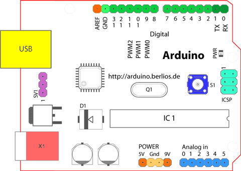
the Arduino has 14 digital pins labeled pin D0…13 (green pins, upper side of board), and 6 analog pins labeled A0…5 (blue pins, lower side of board). When you are using the Adafruit motor shield only the analog inputs A0…5 can be used (and the digital pins 0…2, 13).
If you want to connect your Maxbotix with his analog output to analog pin A4 of the Arduino the answer is yes. If you want to use the digital output connected to digital pin D4 the answer is no, not possible. Because these are different pins. The pinMode function is only used for digital pins.

Picture taken from Arduino tutorial.
BTW. you can use the analog inputs as digital IOs, but than you must use the pin number 14..19. Than you can use pinMode(18, INPUT) for example to use A4 as digital input.
Great explanation!
Thanks, that really makes it easier to understand!
Let me ask another motor shield question: I have the power jumper removed from the shield…I’m running separate battery packs for logic and motors. But it seems like I’ve got some kind of power bleeding through from the logic side to the motors. I’ve noticed that when I have the bot connected to my laptop, but have the motor power turned off, I still get a little bit of LED activity on the shield and some humming, like the motors are trying to run but just aren’t getting enough juice. Should there be any power coming from the processor to the shield if I’ve got that jumper pulled?
Yes, the logic supply is
Yes, the logic supply is going to the motor controller. This behaviour is normal.


