I am currently using a arduino duemilanove, and it is awesome. I have been playing around with it for a couple of days now, and I really like it. Anyways I figured it was time to start to building a robot. I decided to start with the motors. For the motor control I decided to use guibot's tutorial. It worked fine, but the motors only traveled in one direction. Because I wanted the motors to also travel in reverse too I decided to experiment with my own code (on only one motor) that looks something like this:
int motorPin1 = 2;
int motorPin2 = 3;
void setup(){
pinMode (motorPin1, OUTPUT);
pinMode (motorPin2, OUTPUT);
}
void loop(){
digitalWrite (motorPin1, HIGH);
digitalWrite (motorPin2, HIGH);
delay ;1000;
digitalWrite (motorPin1, LOW);
digitalWrite (motorPin2, HIGH);
delay ;1000;
digitalWrite (motorPin1, LOW);
digitalWrite (motorPin2, LOW);
delay ;1000;
}
Not suprisingly, it didn't work. I feel like there is something obvious that I'm missing. The motors go in one direction perfectly, but not in reverse. Can somebody help me to get these motors to also go in reverse?
You’ve only got 2 motor pins
You’ve only got 2 motor pins in your code, are you just running one motor for now? If so, here’s what your code is doing:
• [motorPin1 & motorPin2 = HIGH] Nothing happens here since both sides of the motor driver are at the same voltage. Basically this acts as a weak electrical brake.
• [motorPin1 = LOW, motorPin2 = HIGH] Now we are getting somewhere. With Pin2 set to HIGH and Pin1 set to LOW current is made to flow through the motor, in this case from output2 to output1 (normally I’d label this as the ‘reverse’ direction, since it goes from output2 to output1).
• [motorPin1 & motorPin2 = LOW] This is the same as the option where both inputs were set to HIGH, the motor is held stationary, not very exciting.
If you want the motor to run in the ‘forward’ direction you need to do the opposite of the second command, ie: set motorPin1=HIGH and motorPin2=LOW. That way the current will flow from output1 to output2, thus turning the motor the other way.
Just something I noticed
Just something I noticed aboot your code (no I’m not Canadian:D) was with your Delays, you could use delay(1000); instead of using two seperate lines of code, will save you a byte! 
But as for the motors, what Telefox suggested should work for you.
Thanks
Thanks Telefox and CaptainObvious, that really cleared things up. Yes, my code was only for one motor. Here is my new code:
int motorPin1 = 2;
int motorPin2 = 3;
void setup(){
pinMode (motorPin1, OUTPUT);
pinMode (motorPin2, OUTPUT);
}
void loop(){
digitalWrite (motorPin1, LOW);
digitalWrite (motorPin2, HIGH);
delay(1000);
digitalWrite (motorPin1, HIGH);
digitalWrite (motorPin2, LOW);
delay(1000);
digitalWrite (motorPin1, LOW);
digitalWrite (motorPin2, HIGH);
delay(1000);
}
However now using this code the motor is barely turning and I can’t really tell which way it is going. Am I not getting enough current to the motor? If so how could I correct this problem?
Are you using batteries or a
Are you using batteries or a DC supply? I always check my battery voltage first when things start acting sluggish.
If the power supply itself is ok, the next thing I’d check is that the Arduino outputs are changing like they’re supposed to. If you get a voltage that jumps up and down from nearly zero to nearly the V+ supply about once a second then you can safetly say the problem is not with the code or the Arduino itself.
Also, make sure your ENABLE
Also, make sure your ENABLE pin is connected to the V+ off your external supply. Giving 5volts to the enable pin, well only enables 5 volts!
That was my big problem, I didn’t realize that for the longest time when I was running a fan. And of course, make sure the Grounds are connected to your arduino, that can also cause what seems like low-power. And I would use an external supply, rather than battery, for testing purposes at least.
Well I can say for sure it’s not the code, I just uploaded it and tested it and works fine. (only tested using some LEDs)
But what kind of motor are you using? Do keep in mind, not all motors are meant to be reversed. If you took it out of a, say mini-fan of some-sorts, from my experience, the motors only like to go one-way. They WILL go reverse, but nowhere near the power of their forward. Assuming because they weren’t designed for it.
If you don’t get it figured out, I’ll see what I can do to jimmy-up a ghetto-test rig to help you out with some code.
Best of luck!
Thanks
Thanks guys, I still have a couple of problems with the motor control though :(.
Telefox: I am using the power from the usb cable. Is this bad/not enough power? Also, I don’t believe the problem is with the Arduino because I just got it 3 days ago. I’m not sure if it matters, but it is using the atmega328 not atmega168. I also don’t think that the problem is with the code after reading that CaptainObvious tried the code with a led and it worked. I would try all the testing stuff, but I don’t own a multimeter. I know, I should probably get one.
CaptainObvious: I cant seem to find an enable pin on my board. Is this some specific pin, or does one not exsist on the new duemilanove’s. I am using the same motors as I did on my first robot: http://www.solarbotics.com/products/gmpw_deal/
I think it must be something with the motor reversing. Because it spins fine while regular forward code is put in. Anways I will keep working on it.
The enable pin is on the
The enable pin is on the L293 motor driver chip. You are using a motor driver right? The arduino pins can`t source or sink enough current to drive a motor, you risk damaging the chip without using a driver chip or H bridge.
The USB only provides (at
The USB only provides (at best) 500mA, which may not be enough. The motors you listed are capable of drawing over 500mA by themselves, but that still doesn’t explain the odd ‘forward only’ behaviour…
** I just assumed you were**
I just assumed you were using the motor driver, seeing as you pointed to GUI’s Tutorial.
Enable 1 is for the left side (first motor)
Enable 2 is for the right sight (second motor)
Both enables should be tied to the positive on your power supply. And with the motors you’re using, as everyone suggested, you need a second supply, you never specified whether you’d used a second supply or not.
If you could post a picture, or maybe use Fritzing and show us how you have your circuit hooked up, may be able to answer a few more questions. I’m guessing it’s your power supply though, definately wouldn’t risk trying to pull that from your USB drive, or Arduino. When in doubt, use an external supply! (my new saying?)
ok
Yes, I do have the enable pins wired to positive. That was pretty stupid, I should have known that the enable pin was on the l293d. Anyways sounds like I need external power. I am pretty sure I attach it to GND and VIN, but I’m not sure how much to use…
NOTE: the “9V” pin on the
NOTE: the "9V" pin on the board, under POWER is actually your VIN pin. For testing, you don't need the VIN or the regulator if you have the Arduino plugged into USB. (and make sure if you have the USB plugged in, to unplug the battery/supply, and vice versa.)
The lightning sign is your external supply.. be it batteries or a wallwart.
And I think I missed a capacitor on the regulator, but you'll be fine.
You can change the pins to any pins you would like, but you can use analogWrite(pinNumber, 0-255) to control the speeds on any pins marked PWM.
I hope this helps.. sorry if it's a little messy, have only played with Fritzing a few times. Best of luck, and let us know your results!
That helps alot
Thanks, that helps alot. I will go get a 5v regulator today . I will make that circuit today and tell you how it turns out. If I have problems with it I will post a picture of my circuit. Quick question though, when using the external supply do I also use power from usb/regular battery with it (for powering the board)? I think I do, but I’m not sure.
I’m a bit confused with your
I’m a bit confused with your question, might be late… but
If you’re keeping the Arduino plugged into your computer, for testing code and such, the external supply should only be powering the motor driver. You won’t need the 5v regulator.(but the ground of the motor driver circuit still connects to the ground of the Arduino)
But if you’ve uploaded code, and you’ve unplugged the Arduino from your computer, then you’ll want the Regulator, and you can either use a Usb connector and just power through USB (MUST be 5v, any higher and you’ll fry your FTDI chip), or through VIN( I believe can be up to 9v, but best to stay around 5v as well).
OR
If you have a spare wall-wart with the power-pin that’s the same size of the arduinos, you could use that and hook up the supply to that. Use 1 supply for both without needing the regulator off the board. But you would have to “ruin” a wall-wart for the jack, but helpful if you use different supplies often and want it mobile.
Hope I didn’t repeat myself too much, it’s very late, so excuse anything that doesn’t make sense!
Ok
Yes, you did answer my pathetically worded question :D. I made the above circuit except not using the pwm pins (still using digitalWrite). Now the motors run fine, but not in reverse. With the above code the motors will run then pause and go the same direction, instead of the opposite direction. It will run forward fine, but not in reverse. Any ideas?
Here’s a quick test you can
Here’s a quick test you can try:
• Make note of the direction that the motor does rotate correctly in
• Disconnect the motor from the motor driver, and then plug it back in with the two leads switched (change nothing else!)
• Fire up the circuit again, compare motor behaviour
If the motor now only turns in the opposite direction to the first case, then there is a problem around the motor driver and/or associated circuitry.
If the motor still only goes in the same direction as before, then the issue is with the motor itself, and there aren’t that many things that can go wrong with a DC gearmotor so it’s easy to narrow it down from there.
yes
Yes, when the leads are switched it only turns in the opposite direction to the first case. I think I will try to post a picture of the circuit.
Good idea, maybe the picture
Good idea, maybe the picture will provide us with some clues. So… it’s not the code, Cap’n certified that, the motor is fine, the circuit has proper power now, the enables are set… it’ll be hard to test the parts further without a multimeter, but I wonder if the SN754410 has partly died?
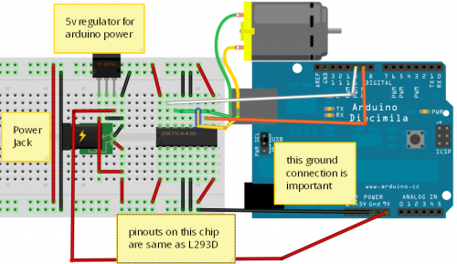
Looking at the diagram on
Looking at the diagram on the drawing, it appears that both Enables and Vss and Vs are all getting 9 volts.
The enables and Vss should be 5 volts, while Vs, the motor supply, can be 9 volts.
With Vss, the logic supply, being at a higher voltage, it may be questionable if the chip can actually read a 5 volt TTL signal.
It probably has survived, just correct voltages should be applied.
In the TI datasheet, pin 8 is actually called Vcc2 for motor supply while pin 16 is Vcc1 for logic supply.
Wooooo
Hey guys, sorry I’ve been gone so long. After getting home I was about to take the picture when I saw the post from robologist. I tried it out and it worked like a charm. I now have a motor that runs forward and reverse. Thanks to everybody who helped. My robot is now on the way.


