


i2c_servocontroller.bas (574Bytes)
i2c_masterforpicaxe.pde (487Bytes)
While working on my first Arduino project I found out that servo library is not compatible with software serial library which is very bad for my project. So, I thought: What about making my own servo controller of say... Picaxe 28x1 chip??? Which will communicate over serial...Doh!... servo command won't do... hmmm... I2C!!! Quick search trough manual, and.... TARAM!!! hi2csetup command just gives you all you need!!! :
- Ability to configure Picaxe as I2C slave (for 20x2, 28x1, 28x2, 40x1 and 40x2 chips only)
- I2C functions absolutely automatic (i.e. should not be any interference with servo command for example)
- Giving all 128 (X1, 20X2) or 256 (X2) bytes of scratchpad area for memory transfer
- hi2cflag flag set when master writes to our chip
Sounds very promising to me! So lets get started. My setup: Picaxe 28x1 on breadboard + Arduino Duemilanove.
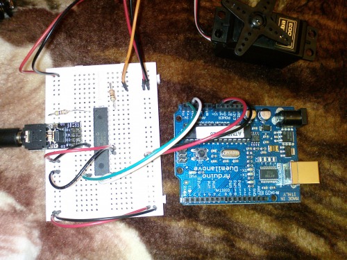
To connect 2 mCUs you need just 2 wires: Picaxe 28x1 pin 14 (i2c clock) to Arduino analog input 5 and Picaxe pin 15 (i2c data) to Arduino analog input 4. Arduino has pullup resistors for I2C built-in, so you do not need to mess around with resistors.
My Picaxe I2C slave code for use of byte 0 of scratchpad to control servo on outpin 0. You can add more controls by just adding case branches for other servos or whatever you desire!
1 'Servo controller for IMP21
2 '6-jun-2010 by Isotope
3 'v1.0
4 '
5
6 #no_data
7 #no_table
8
9 'addr | control
10 '--------------------
11 '0 | servo @ pin 0
12 '
13 '
14
15 hi2csetup i2cslave, 160 '80 on arduino
16
17 put 0, 150 'initial position
18 servo 0, 150
19
20 main:
21
22 if hi2cflag = 0 then
23 goto main ' poll flag, else loop
24 else
25
26 hi2cflag = 0 ' reset flag
27 get hi2clast,b1 ' get last byte written
28
29 select case hi2clast 'what address in scratchpad it was written to
30 case 0 'ok, address was 0
31 servopos 0, b1 'which is our servo 0 slot. Move it.
32 endselect
33
34 goto main
35 endif
Ok, little bit of explanation here:
line 15: setup Picaxe as I2C slave with adress 80. We have 160 there as bit0 of address is read/write flag which is ignored in our case, so to shift 80 one bit to the left we have to muliply it by 2, that gives us 160.
line 17-18: initialize scratchpad byte 0 with value of 150 (servo center position) and move servo into that pos.
line 22: We continiously poll the hi2cflag to see if master wrote something to us. when it becomes 1, first we have to clear the flag by ourselves (line 26) then we can get last written byte to b1 (line 27) and deside what to do with it upon address it was written to (lines 29-32). Thats it! My servo controller code for one servo is ready.
Now lets move to Master (Arduino) code:
#include "Wire.h" //We need this library to operate I2Cbyte pos; //Position of servo
void setup(){
Wire.begin(); //Initialize I2C
delay(300);
}void loop(){
for(pos = 100; pos <= 200; pos++){
Wire.beginTransmission(80); //Init transmission to address 80
Wire.send(0); //scratchpad address we want write into
Wire.send(pos); //data we write - position of servo
Wire.send(0); //Just add this
Wire.endTransmission(); //finalize transmission
delay(200);
}
}
What we do here is pretty much explained in comments to code. Just one thing to mention is format of messages: First byte to transmit is the scratchpad address we want to write to, second is data byte. I figured out by trial and error that communication won’t take place if you specify just address and data byte, you need to write 3rd byte of whatever (I did write 0) for all of this to work.
Now we have our very own servo controller!!! Just add more servos, LEDs, motors, whatever and controll it all over I2C from Your Arduino board! 
I have tested it with just one servo and it worked perfectly
Enjoy! 