Arduino based PC Footswitch

enclosure.jpg (1119336Bytes)
cut.jpg (1090798Bytes)
Footsie.jpg (1765773Bytes)

UPDATE - I have reworked this project to use a Line6 footswitch to act as the buttons, connected to an arduino 'control box' via ethernet cable.

I will update this post over the coming days.

I am in the process of putting together a project for another hobby of mine; music. I am a trombone player, who dabbles with many many other instruments, playing in many types of bands. I play in a Band called Dennis, in addition to Westoe Brass Band, and also play for many others as and when duty calls or opportunity knocks.

Recently, along with a like minded friend, I have started to conjure up a nice little portable recording rig to allow us to record whenever and wherever we like, whether it be on lunch breaks at work, at home etc. Essentially freedom to record without the studio constraints is the aim of the game.


Concept - one briefcase-like case (flightcase, pellican case etc, all dependent on what i can acquire) with one IEC socket will be plugged in to provide power to the rig (one laptop and two fire wire interfaces).

Foot controller - Bearing in mind most brass instruments take two hands to wield and we may be recording on our own, I want to add some kind of foot control system to the build, to enable ease of use. Having read about the ability of the ATMega32u4 to appear and function like a HID such as a keyboard my mind set to work; why not use one to send keystrokes to the Laptop with footswitches?

Keyboard shortcuts could be configured using something like AutoHotKeys, allowing full control of the laptop and the recording software's features while being able to concentrate on the task at hand.

***Pro Micro 32u4 ORDERED - AND RECEIVED!***

I'm thinking that it will be quite a simple circuit for the box; all the switches will be wired up to 5v, and the other side of the switches will be wired to pins on my new pro mini and to ground (via 10k Resistors to avoid creating a short).

Unsure of how yet but when the Pro Mini detects a change in state a void for that button will send the keystrokes to the laptop.


***24/07/2014 UPDATE***

Managed to get my little Micro firing some "IT'S ALIVE!!!!!!!" text to an open text document. I don't have any switches purchased for the build yet, so just using a jumper to bridge 5v to my data pin/ground.  Some switches would be lovely!

Next step is to add more buttons to my rudimentary code and also increase functions it carries out.

I'm also looking to add a little 16x2 display (using the I2C converter board to save pins), and also a selector switch to allow multiple layers to be assigned to the buttons.


***07/08/2014***

It has been a very long time since I've been able to do anything remotely fun with any of my projects due to work and band commitments over the last month or two. While work has not let up i am hoping to get some more of this project done!

I have purchased 5 momentary footswitches and have been given a 6-position selector switch; if I can these working I'll be able to have 30 commands at my disposal. I have my pro micro breadboarded and 4 'switches' set up, plus have decided to try and incorporate 2 16x2 lcd displays to give me more room to display button functions etc.

In order to save pins with the selector switch i am going to use a series of resistors in conjunction with the selector switch to return different values to one analog pin based on which pin is selected.

Coding work is underway too - I'm looking to use some arrays to map out what void should be triggered based on the current selector position and what button has been pressed.

I am aiming to have my code check what position the selector switch is in and what button has been pressed and then return a function name from an array of strings. Then using some if, else if and else statements fire the intended key commands.

The LCD screens will display the array information for each of the buttons based on the selector switch too.


The use of arrays,, i2c screens and buttons etc is something  completely new to me, so it's a long journey to get in functional!


***UPDATE 08/08/14***

Good news - an enclosure has been found! I found an old portable banner stand that was being thrown out, so i saved it from the skip, took out the innards and essentially cut it in half. I have cut holes for the 5 switches and potentiometer, however I'm contemplating getting a bigger screen to put in the project.

enclosure.jpg


cut.jpg

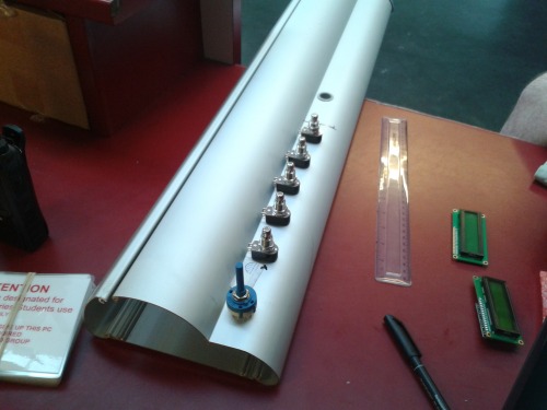
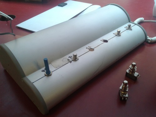
Before and after hacking :-)

The switch holes need a bit more work but i have ran out of time - that will happen Monday.


Code has took a big step forward today too - Now the code checks the values from the pressed button and also the selector switch and returns a string from the Array. It then processes the key commands associated to that string. Wahey!!!!

Now i just need to sort out the resistor series for the the selector switch, as i currently have the code just defaulting to position one for now.

Once that is done i will wire up my switches to my Pro Micro, add the USB port to the enclosure etc and then give it a go!

Then screen work shall commence...


*** UPDATE - 15/08/2014 ***

Here is a pastepin link to my current sketch so far:

http://pastebin.com/PYaaASVU

As it stands It all works nicely - apart from the for loop checking the button pins.

It will detect button presses, however only sequentially - it's as if it sits and waits for each of the buttons to be pressed before moving to the next button.

My head hurts! Any suggestions would be greatly appreciated (thanks already to lumi and bdk6 for helping!)


More work to follow hopefully!

4 x 20 screen ordered!
Going to have a stab at fitting my menus on this, or this with the 2 x 16. If it doesnt work, and i’m feeling somewhat devil-may-care, I may order a tft or touch screen :slight_smile:

Ironing out the code

While waiting for the Screen to arrive I have been working on the code for my footswitch.

While still very messy I have improved the way it is written by using some FOR loops when going through and setting up pins and reading pins etc.

This way, if I decide to add more buttons to the footswitch I can just add the pin number to the array of Buttons and add their functions to the ButtonMap array; The code itself will require no work to incorporate the new buttons.

I am currently awaiting (in addition to the screen and a USB port for the side of the enclosure) for some 2k resistors to turn up.


When I receive them I will be creating my Resistor Ladder for my 6 way switch. Once this is done I will be able to complete the void for defining the switch.

Then the Screen void is to be tackled.


Once my code is complete and tidied up I may post my code, in case it is of any interest to anyone.

Resistor ladder complete!

My 2k resistors arrived and i was able to get them soldered in series on my board, attaching points to some header pins - will add a picture of the board soon.


I have had a chance to test my code a bit more and it needs some work.

In my main loop i am calling a void to check the value of the selector switch, which works fine, then a void to check button presses. This part uses a For loop to go through each of the button pins and run an if statement to check for a change of state.

It does detect presses, but only if buttons are pressed sequentially. Then once it has gone through the 5 buttons it hangs, and does not allow the code to loop.

Crumbs.

Interesting project. For

Interesting project. For casdes like that, reading buttons and easy adding them physically and then in the code you may check the SWITCH CASE function http://arduino.cc/en/Reference/SwitchCase

I am using it in several occasions and can recommend it.

Thanks buddy!

I had been looking at using a switch case statement for handling the ToRun statement, however it doesn’t work with the string values i have in my array.

My main issue is reliably monitoring the 5 button pins reliably, checking their states and launching the intended function if the state has changed.

I shall post my code in the next comment and will try and explain my logic!

Here’s the offending bit :slight_smile:

I have included my globally defined values to make more sense of it:


String ButtonMap[6][6]={
{“1”, “PlayPause”, “FF”, “RW”, “VolUp”, “VolDwn”},
{“2”, “NA”, “NA”, “NA”, “NA”, “NA”},
{“3”, “NA”, “NA”, “NA”, “NA”, “NA”},
{“4”, “NA”, “NA”, “NA”, “NA”, “NA”},
{“5”, “NA”, “NA”, “NA”, “NA”, “NA”},
{“6”, “LockPC”, “NA”, “NA”, “NA”, “NA”}};

//Pins to be used
int ButtonPins[]={4, 5, 6, 7, 8};
int SelectorPin = A3;

const int ButtonCount = sizeof(ButtonPins);
int PreviousState[ButtonCount];

//define variables to hold Selector switch position, button pressed and the associated function to Run
int SelectorPos;
int CurrentPos;
int ButtonPressed;
String ToRun;


void ButtonScan(){
/*Use a For Loop to go through the button pin array checking all states - any changes then check SelectSwitch() and somehow
fire the void associated in the ButtonMap array.
In theory the array should be accessed such as ButtonMap[SelectorSwitchValue][ButtonPressed]]  */


int State[ButtonCount];

for (int ThisPin = 0; ThisPin < ButtonCount; ThisPin++) {
  //Loop through buttons checking state, run ProcessPress if button pressed
  State[ThisPin] = digitalRead(ButtonPins[ThisPin]);
  if ((State[ThisPin] != PreviousState[ThisPin]) && (State[ThisPin] == HIGH))
    { ButtonPressed = ThisPin +1;
      ToRun = (ButtonMap[SelectorPos-1][ButtonPressed]);
      ProcessPress();
      PreviousState[ThisPin]=State[ThisPin];
    }
  }
}

bdk6, I could kiss you!!

Made the updates that bdk6 suggested to my code, and it now works!

The line that updates the PreviousState was indeed trapped inside the if statement instead of being after it in the for loop.

In my defence I was only a line away from having it in the right place :slight_smile:


Now to finetune the code and add in some debouncing to stop the button presses triggering more than once in error, and adjust the values for my selector switch.


Today is a good day!!!

I am glad that you solved

I am glad that you solved your code problem.

However, since reading your project the first time I am thinking "how the hell will Craig push those buttons with his foot/toe (considering you don’t wear shoes.

Do you have some pedals which you use to attach to that buttons?

PS: I once was doing the sound and light in a rock band, so I know what a foot switch has to look like…but yours does not look like what I remember :slight_smile:

Thanks lumi!

Cheers buddy - the more i fix my code the more I want to add to it, ha ha!

Once I have my debouncing coding sorted i want to add code to differentiate between a button tap and a button being held etc to increase functionality. Plus my 20x4 lcd screen arrived today, so also going to start adding the menus to it too.


As for pressing the buttons they work well with all kinds of footwear - not a fan of barefoot :slight_smile:

The buttons themselves are quite common on a lot of guitar stomp boxes; while the likes of Boss and Digitech tend to build the button into the pedal chassis a lot of other pedal companies use the style of switch I have used. One of my favourite pedals I own is the Yamaha Magicstomp, and that features three of the buttons I have used for switching patches and suchlike.

My only gripe with my current design is the buttons are a bit close together. It’s not really an issue as long as I’m careful, however I am hoping to create a proper enclosure with some leds etc in. Once I have the thing working properly, that is!

Well, the code is never

Well, the code is never finish, there is always something you need/want to improve.

For the buttons, yes they look a bit small on the picture but if you say they are common used for that purpose it’s ok. Yep, taking a look at my feet it might be nearly impossible for me to only press one button with shoes :smiley:

That’s why I love coding!

You are right buddy, coding is never finished. That’s what I love about it!

The buttons are quite small, however very robust :slight_smile:

I think when I rebuilds menclosure I’ll be aiming to put the buttons in a zig zag pattern (two at the top, three at the bottom) rather than all five in a line - that way I’ll be able to make them more shoe-friendly and increase the space between them whilst not having to radically increase the size of the controller.

Once the controller is rebuild I’ll be designing a case for the laptop, firewire interfaces and power supplies to live in and then signing this one as complete - then back to more robot like projects! :smiley: