Hey everybody, I am looking for help with this project: https://www.robotshop.com/letsmakerobots/node/7752
I need to make a device for a school project that detects IR position for a PC mouse but that incoporates a
microcontroller, so this project seems like a good start.
I have already built the voltage regulating circuit, removed the IR sensor and attached it to the circuit. All
voltages seem to be at desired values.
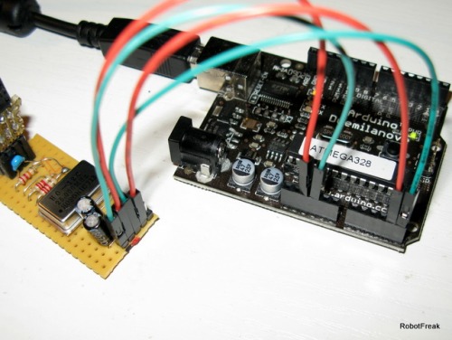
But I have a strange problem. The project calls of a Duemilanove board, which I have, but the tutorial does
not tell you how to connect the circuit to the board. And the attached video does not use the board at all.
The tutorial links to a German wiki that says to connect SCL to PC5 (I assume that would be Analog Pin 5) and
SDA to PC4 (I assume that would be Analog Pin 4).
So I do this, but the board stops transmitting as soon as I plug in SCL and SDA. In the Arduino IDE serial
monitor, a bunch of zeroes are displayed using the provided sample code. Same goes for hyper terminal in
Windows. The zeroes stop coming as soon as I plug in SCL and SDA, and the zeroes resume when I disconnect
them. Additionally, the voltage at the SCL and SDA pins drops from 3.3V to 1.8V (on the circuit).
I get no blobs using the Wii-Blobtracker software provided in the tutorial.
The only thing I can think of is that maybe I fried the sensor when I removed it from the remote? It looked
fine, is there any other way to tell for sure?
If anyone has any experience with this project, I'd appreciate any help.
Thanks in advance.
I have used a selfmade
I have used a selfmade Arduino board for this project, but it should work with a Duemilanove board. Connection should be made between sensor and Arduino: 5V to VCC (not Vin!), GND to GND, SCL to Analog 5, SDA to Analog 4.
But you should not plug in the sensor while your Arduino is powered. First connect sensor with Arduino, than power on the Arduino. The sensor needs an initialisation sequence, and didn’t work without it. There is no detection in the software to detect that a sensor is plugged in, no plug and play.
Thanks for the quick
Thanks for the quick response.
I’m afraid when I do what you suggested, the result is the same. For example, the sensor is connected while the board is off. Then I connect the board. The led on on 13 flashes a few times then goes out, when I click connect on blobtrack, nothing is picked up (my COM port is not picked up and there are no coordinates). As soon as I disconnect SCL and SDA, the board starts transmitting (the TX led starts flashing) and I am able to connect to blobtrak, but of course it picks up nothing but zeroes.
I have been connecting to 5V and not Vin.
Maybe the sensor is bad? Time to sacrifice another Wii Mote?
I don’t know if you still have this project built, but what voltages do you get at the SCL and SDA lines when connected? What voltage should I see from the crystal out (I get about 1.4V)? My Voltages for SCL and SDA are 1.84V when connected to the board but 3.34V when disconneced.
Thanks for the help.
Ok, I’ve done some tests
Ok, I’ve done some tests with the sensor on a Duemilanove board. It works, as expected, without any problems. I measured 3,3V on the I2C lines and 2.2V on the Oszillator output when the program is running.
Do you use a quarz oscillator or a normal crystal? A normal crystal will not work.
I’ve tested what happends when you crossover the SCL and SDA lines. The sensor gives only 0 values, but the board didn’t stop working.
I remember one guy have a problem to get the sensor running. After he replace the capacitor and resistor on the reset line and tight the reset line directly to 3.3V the sensor works.
I’m using a Quarts
I’m using a Quarts Oscillator (Motorolla K1100AM 24MHz - 4 pin). Ive tried what you suggested. I connected the reset pin to the 3.3V source on the D-Board and on the cirucuit (I removed the ceramic capacitor and 22kOhm resister.)
I’ve also tried with another crystal oscillator this time only 20MHz - 4 pin, in all combinations (with resistor and cap, w/o restor and cap, directly to 3.3V from D-board, on the circuit). I get 2V only using the 20MHz crystal, but only 1.4 or 1.5V using the 24MHz oscillator.
The result is the same. D-board doesnt transmit unless I remove the I2C lines.
I’m going to rebuild the circuit. I’m using a small bread board piece (new) (have to because of school). You think maybe you can show me a pic of how you connected everything (to the board at least)?
or maybe i can show you a pic of what I did maybe you can see whats wrong?
I just think maybe I fried the sensor when I desodered the thing. I used desoldering braid and a desodering iron. This time I will just use my Dremal and cut the damn thing out 
I appreciate all your help in this,
Thanks again.
Could be that you fried the sensor
Could be that you fried the sensor. A hot air gun is highly recommended to remove the sensor.
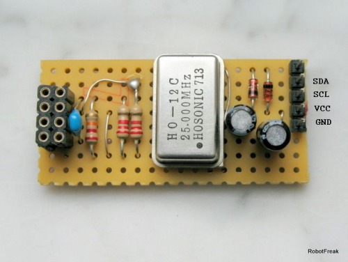
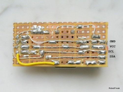
Here are 2 pictures from my sensor board:
**Hey,Sorry i didnt realize **
Hey,
Sorry i didnt realize that you had already included a photo, it didnt show up when I replied.
Well I ended up getting another Wii remote and after making my circuit a little neater, just sawing the sensor out with a Dremel, and taking my time soldering, I finally got it to work.
Thank you so very much for all your time and help.
Hey how are you?
Hey how are you?
Well all went well with the demonstration of this project in class, but now I need to move on.
I was wondering how to connect the sensor to the PC via USB, without using the D-Board.
I have my board setup with the ATMega328. I added USB-B female plug (the fat blocky type) to the board. I still need to get some capacitors, but as far as the USB goes, do I just simply wire D+ and D- to Pins 15 (USBDP) and 16 (USBDM) on the ATMega328?
I don’t need to be able to program the ATMega328 from the homemade board, just be able to send the data to the PC.
The reason I ask is because my teammate also has to be able to send data from the ATMega328 to the PC, but he was unable to do so; I just don’t want to run into the same trouble.
A rough schematic would also be appreciated.
Thanks again.
I don’t really understand
I don’t really understand what you plan to do. The Atmega328 has no build in USB capability. The only way I know is the V-USB firmware to build an USB client in software with an Atmel controller. The Metaboard schematic is maybe helpful.
Sorry if I wasn’t clear.
Sorry if I wasn’t clear. You know how the D-board transmits the data from the Wii sensor to the PC via USB? I need to be able to reproduce this as I can’t very well use the D-board in my final design.
I have seen some people use a max232 chip (or similar) to communicate with the PC via an RS232 serial cable. Like this guy.
Or they have used an FTDI cable. But I figure they use this cable because it allows them to program the ATMega while on the homemade board (without having to remove the chip and put it beack in the D-board for reprogramming.)
I’m trying to avoid this because 1.) I have to incorporate USB in my design (RS232 is outdated) and 2.) I’m trying to keep the cost of the design down, for my sake and the project purposes. The FTDI cable is $20.
From what I can tell in the video posted in the How-to of the Stand Alone Wii Sensor, it has a simple homemade board with the ATMega attached but I cannot make out the circuitry or if an FTDI cable was indeed used.
If an FTDI cable was in fact used, then ok how to use it? But if i can do the same with $5 worth of components, then even better.
I will take a look at the schematic you sent and see if can use it.
Thanks again.
OK, now I understand what
OK, now I understand what you mean. In the video for the Stand Alone Wii Sensor I’m using a selfmade board with an ATmega328 with Arduino Bootloader and a FTDI cable to send the sensor data to the PC.The Arduino board has also a FTDI Chip onboard.
If you don’t want to use a FTDI cable, the Metaboard is the best way to go. But you will need an ISP programmer to program the special bootloader into the ATmega for the first time, or without using a bootloader the programs. If you don’t have an ISP Programmer, you can use the Arduino board as ISP programmer.
Hmm…
Hmm, I think I may need to try both, see which pans out better. Sounds like the FTDI cable is the easiest but more expensive way to go.
I will try both but as a general rule, how do you wire the data cables?
For example, following the schematic for the D-Board on the Arduino homepage, I have the following connections:
From the Wii Sensor to ATMega328: SCL to Pin 28 (ADC5)PC5 & SDA to Pin 27 (ADC4)PC4.
From ATMega328 to USB: Pin 16 (PB2/USBDM) to Pin 2 of USB & Pin 15 (PB1/USBDP) to Pin 3 of USB.
From what I understand, this should work if I have a FTDI cable from Sparkun.
Else I need to go the Metaboard route. If so, is the wiring the same, or do I have change the wiring as well as the code (for the Wii Blob Tracker)? I have to add the special bootloader in additon to the Arduino bootloader the ATMega328 came with?
Thanks again.
Here is the picture for the
Here is the picture for the Arduino clone board I’ve been using for the Wiimote sensor.
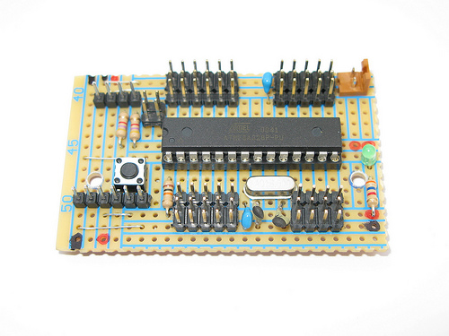
A picture with detailed mouse-over notes can be found in my Flickr album. On the left you can see the 6pin Header for the FTDI cable and the 4pin I2C Header.
The FTDI header pinout from left to right is:
- GND
- n.c
- VCC
- TX-O goes to Pin2 (PD0, RxD) of the ATmega
- RX-I goes to Pin3 (PD1, TxD) of the ATmega
- n.c
The I2C Header pinout:
- GND
- VCC
- SCL goes to Pin28 (ADC5, PC5, SCL) of the ATmega
- SDA goes to Pin27 (ADC4, PC4, SDA) of the ATmega
Hey,Sorry i didn’t reply
Hey,
Sorry i didn’t reply sooner. I got really sick with allergies.
Anyways, thanks for all your help, I’ve ordered the stuff I need from Sprakfun and I will try it out a soon as I can.
Thanks again.


