

Yes, try those
Yes, try those transistors.
And look for a lower current motor, similar to the pololu one I linked to above. Stall current of around 800mA, etc.
Good luck!
Yes, try those
Yes, try those transistors.
And look for a lower current motor, similar to the pololu one I linked to above. Stall current of around 800mA, etc.
Good luck!
hey can i series to IR led
hey can i series two IR led right?? and minimize the R1 to adjust the range. up to?
Yes, that would be ok. R1 at
Yes, that would be ok. R1 at around 150 ohms or so for an IR LED current of around 25mA.
haha. sumthing went wrong
haha. sumthing went wrong while im testing it again… sumthing smoked… but i think it’s shorted… may be i connect some wires… hah… this weekend im gonna buy new components and ill directly put it in PCB… maybe ill use presensythised PCB… wish me luck… thanks for your help joC… you help us a lot…
No worries, aidzmana. I hope
No worries, aidzmana. I hope it all works out.
IC chip
I would consider an IC comparator chip as a brain. What do you think they did for brains before microconrolers? FYI I’m an oldschool robot designer who uses no microcontrolers only ic chips or no chips at all.
If IC chips aren’t an issue
Here is a link to schematics that I designed that are very simple.
Using a commercial sensor
Using a commercial sensor would certainly simplify matters, and I was possibly somewhat remiss in not suggesting it as an alternative.
I suppose there are many ways to do this. The approach I offered, which I thought was a simple and accessible starting point, but which could definitely stand some tweaks and improvements, is only one.
i would like to try dis i
i would like to try dis
i will just put this h-bridge in relay

hmm. but i want to reproduce it twice.. should i use dual timer? or just simply reproduce the RECEIVER and relay?
Just use one 555 and
Just use one 555 and duplicate the receiver circuit.
thanks dude…
thanks dude…
’ullo, you’re back! Couple
’ullo, you’re back! Couple of points:
The h-bridge is not a drop-in replacement for the relay.
Regarding the h-bridge you’ve shown, you won’t be able to drive the upper NPN transistors into saturation unless the h-bridge voltage is a couple of volts lower than the control voltage.
Saturation in h-bridge transistors is A Good Thing.
If you are still going to use a single supply for both control and motors, I can suggest other h-bridge configurations you can use. Also if you want to drive the motors from a higher voltage than the control voltage.
If you keep the 74HC14, you can use a couple of its inverters to drive the h-bridge, and use another inverter to make your oscillator, obviating (that’s a good word, isn’t it!) the need for the 555 chip.
P.S. Did you end up swapping out those high current motors?
yeah i change my
yeah i change my motors…
im using two supplies 9v… 1 for the sensors and 1 for the C, NC, NO in relays…
im using this logic

Have a look at The Roach
This is an brainless easy to build robot.
Well, now I’m completely
Well, now I’m completely lost.
If you’re using the IR receivers to trigger a couple of SPDT relays, where does the h-bridge fit in?
thats looks great what motor
thats looks great what motor did you use?? my prototype of that circuit also works. hmm. maybe its just because of my motor… and sensor i use.
I used these motors from
I used these motors from Altronics:
http://www.altronics.com.au/index.asp?area=item&id=J0015
The phototransistors I used are from Jaycar:
http://www.jaycar.com.au/productView.asp?ID=ZD1950&keywords=phototransistor&form=KEYWORD
I can’t remember where I got the IR LEDs, but I’m sure most would be fine.
I need the 74HC14 to drive the transistor h-bridge, but I will try the other circuit I posted, where I attached the sensor directly to an L293D. With the reduced delay resistor. Should cut out half the wires I’ve had to use!
You could still go ahead and use some 38kHz sensors to drive some relays, but I imagine you’ll still have to introduce some sort of small delay to the sensor output, to extend the motor response. Shouldn’t be too hard, I suppose.
Or spend a bit more money and go for some Sharp distance sensors. Still use the comparator to set the threshold, just change the inputs as the Sharp sensor output rises as an object comes closer.
BTW, I only used one potentiometer in my mockup to set both sensor thresholds. Consequently, the 'bot ‘sees’ quite well out of its left eye, but is almost blind in its right eye. Sort of like my old uncle Fred!
For anyone casually
For anyone casually following this topic:
I’ve done a really quick mock-up of the circuit I posted earlier, and it works fine, 'cept for one thing!
The sensor works well, until you add the motors to the mix. (How often have you heard that?)
It took me about half an hour to do a quick lash-up, using CD’s, doublesided tape, and a breadboard. I then spent about an hour troubleshooting.
It appears the trouble is the 1Meg resistor in the delay components. Works fine, until you start the motors. Then a mysterious voltage appears across it, as it did in the 2nd circuit with the L293D. I should have realised then. Another reminder of the hazards of high value resistors in noisy environments. Any small currents generated by the motor noise get transformed into large voltages by the large resistor.
Dropping it to 100k, and upping the capacitor value did the trick. So maybe the second circuit would work as well. I’ll check later this week.
The amended circuit:
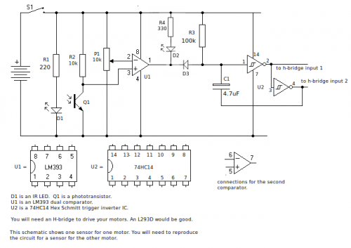
I used this h-bridge:

Link to video of dodgy lash-up!:
http://www.youtube.com/watch?v=h3CShwF19vQ
Things to watch for in video: Funky desk fan, cat food, cornflakes, sensor indicator lights, ugly carpet, cute puppy.
how you do that only one
how you do that only one potentio?? IC1 pin 2, and 6 are connected to the base of potentio?
Yes, that’s right. Adding in
Yes, that’s right.
Adding in the indicator LEDs really helps to set the potentiometer.
edit: I’ve put some photos on a blog page, if that helps: