

The PWM signal line that goes to standard servos cannot be bussed.
Sorry Nick and others. Andy sounds like he is fairly involved with the open servo project and the reply was directed to him so I was trying to balance the techno talk against lay speek, but at the same time did not want to loose the rather technical points I was attempting to get out for discussion.
Pete gave a pretty good description/breakdown of the terms I used to describe the different power distribution techniques.
Andy, I’ve never tried using I2C in the configuration you mention but you may want to make provision on the servo(s) to allow for distributing the pull up resistors on SCK and SDA, or at least distributing them on the end point servos of each chain. One downside to a star distribution scheme is each leg will have a different impedance and you will get multiple signal reflections superimposing upon each other after each edge. In the scenario you describe you are introducing multiple loads on a chain and then connecting several chains as a star. Since each load creates some amount of reflection you are potentially creating quite a complex composite reflection. I don’t know if the reflections will last long enough to create communication problems but, again, it is another one of those nagging thoughts that I thought may be helpful to mention. You could always model this as transmission lines in pspice to analyze it but… yuck. heh. 
I’ve never worked with HQX or 1-wire myself but there is a fair amount of information available for it between the maxim/dallas and TI websites. TI uses the HQX to talk with their battery charge controllers so be sure look in there for application notes if you are interested.
You know actually if you could assign each servo an address in the chain then you “could” encode the PWM signal exactly the same way it is transmitted in an R/C radio, 20mS frame broken into 2ms windows with each channel being in its window… just sort of skipping the whole RF part in the middle.
You’re talking about adding some sort of an external preprocessor to each servo though, right?
Well, not really. If you are talking to these open servo things with I2C you must already have a way to assign a unique address for each servo, right? So if the micro in the servo can read a standard servo signal (for when it is not being used in the I2C configuration, i.e. as just a servo) it could just as easily be programmed to decode “its” signal from the composite frame using that I2C address to determine which of the 9 channels in the frame belonged to it.
This is all just hypothetical of course… you would be limited to only 9 channels per “chain”, using the standard FM r/c radio composite frame. I don’t really know why you would want to apply this when you already have a purely digital bus available, other than it would be a single wire type of protocol. If you wanted to get really crazy with it though you could code a small CPLD (big PAL, non-volatile fore runner to an FPGA) that you could “write” a PWM value to 1 of 9 “registers” from your host micro and the CPLD would encode and transmit the composite frame. This would offload the host micro of the timing critical chore of building the frame and transmitting it. Lattice has several small 4000 series parts that would do this easily (and I’m sure xilinx would have parts capable of doing it too.)
ok, I think we just confused multiple topics… I was replying that you couldn’t bus standard, unmodified servos. I thought you were addressing that same topic…
uh, ok, yeah you are right you would need something in front of the standard servo to set an address and decode the frame. Sorry. I went on the tangent of a modification of the open servo design to include the decoding so you could effect a simplistic single wire daisy chain of several of them (despite my earlier power distribution concerns of course.) 
quick update:
Back up and running on a new Gumstix. Now using the unreasonably uncommon screws that hold the things together. The Robostix expansion board is working as expected, I can flash it with the Gumstix via uISP. The I2C bus is up and running, level shifted to 5V via the Robostix board. Communication to a couple of OpenServos has been a success via the /dev/i2c-x interface.
Did some quick and dirty proof of concept bridging between the servos and a remote socket connection. Went smoothly.
TTL serial to USB adapter running off the console port on the robostix as well (I was originally using a tweener). I’m sure this will come in handy for when the wifi card decides to not find the network, I’ll be able to just plug a laptop into the side of the bot and watch/help it boot.
Gaining some confidence in the latest OpenServo hardware revision, about ready to order enough boards to be fabricated to build 18, already have the components.
I’ve placed a brazillion orders for all this necessary bits to do home PCB etching for building the power board. Most everything has arrived except the most important bit (the chemicals) for which I failed to hit the final really-commit-the-order-I-actually-want-you-to-send-it-to-me button, setting me back a week or so. At least they still had my order in the shopping cart when I returned 
Worked out the design for a tiny little board that will rest on each leg driving only a momentary button and 3 colored LEDs for debugging purposes. I had found that even though I made a spiffy rendering of the bot on the PC interface, it was tough to watch the feedback displayed on the screen and to see what it’s reacting to in the real world simultaneously. Simple things like knowing whether or not the ground contact sensor engaged while its running some of the posturing code was difficult. So in comes little UIs on the actual bot that will be used to indicate whatever is of interest at that moment in development and to allow some simple interaction with the code via the buttons to do things like shut legs down or change the modes in which they are operating. My first stab at is awfully damn small but single sided. Hopefully it won’t be too ambitious for my first etch.
Very interesting update, even though half of what you said is jiberish to me. 
Do you have a pic of the gumstix system installed on your hex? I would like to see how you have things setup.
The gumstix isn’t yet installed on the hex. I’ve got to work out some sort of a deck system as I went with the alum chassis.
Heh, I’ve had experience with those “really-commit-the-order-I-actually-want-you-to-send-it-to-me” buttons before.
You’d think that you were launching a hellfire drone, what with all the double-checking some sites do.
Next thing, you’ll need to turn two keys sycnronously.

Anyhow, your whole project revamp sounds really neat.
I’m interested in hearing how good the position/strain feedback from those new Open Servos are.
Since I’d have to pay for an entire new set of servos, when HiTec starts selling the new ones, to get that from my current ones, I’m thinking about jumping onboard.
Those LED’s sound neat, too.
I was thinking about doing adding LED’s to my bot just for fun, but no one makes black ones.
Sweetness.

Then I shall wait and follow our leader.
The larger motor Open Servos would be amazing, especially if Jim makes SES brackets just for them.
That just opens up so many possibilities.
Perhaps a child-sized biped…
or a normal-sized biped with gobs of power…
The only problem would be powering the beast without weighing it down too much.
Hobby servos draw enough current as it is.
Perhaps LiPos would be necessary.
Does Robo-One have a size limit?
BuilderA: Wow, your robot has huge arms!
BuilderB: Those are his fingers. 
That depends on which competition it is.
Most competitions that I’ve heard of use the rules that can be found at www.robogames.org/
ugh… that was a lot of soldering. 18 OpenServo boards ready to go!
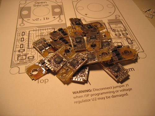
Now on to cables and connectors
Did you enjoy smelling all that flux? I bet you smelled flux for a few days afterwards huh?
yea, I’m pretty sure I’ve got a low level lead poisioning too
This is going to be very interesting to see your creation use these things. I look forward to seeing some video of it in the distant future.
Those look neato!
Such tiny tracings.
Sorry, Andy, you’ll get no pity from me.
I love soldering (probably because it’s the only part of electronics that I’m not vastly inept at).

Is it just me, or does that picture make one feel like diving into a swimming pool filled with Open Servo boards.