For a lot of reasons:
The aluminium chassis allows me to constantly pop servos in and out (important since OpenServo is still in its infancy) as well as to share in solutions others might find for ground contact sensors (which have been the bane of my existence for a while). I’ve also managed to crack bits of the lexan by constantly screwing in and unscrewing certain bits and over tightening them.
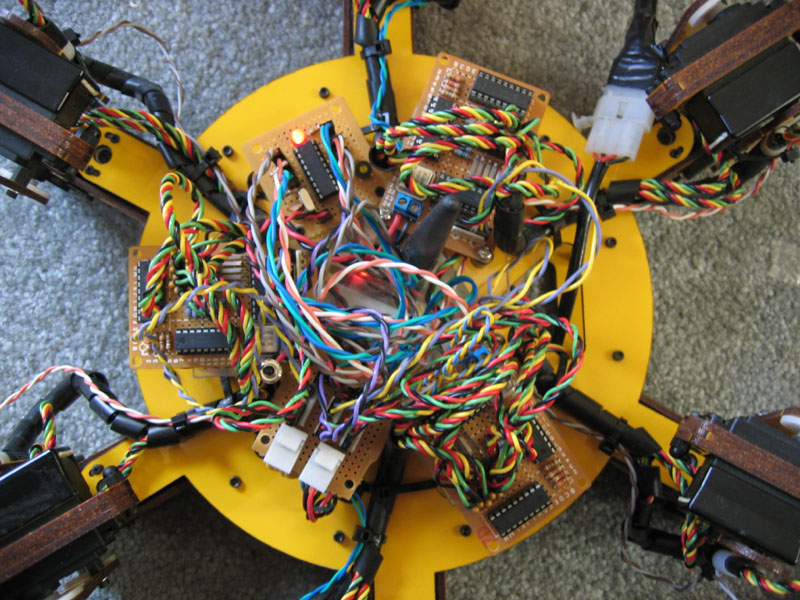
The Gumstix mostly because its cool. I’ve been looking for a good excuse to learn Linux and this is a great one by my measure. As my current bot has progressed, I’ve just been tacking on more and more PIC microcontrollers. At the moment there are 12 and I can see the need for a few more. All those processors are “dumb” in that all the real number crunching and high level processing happens remotely on a PC communicating with the bot over 802.11b. The gumstix will give me the option of putting the higher level, processor intensive code onboard while still retaining the ability to slave the device to a PC over the network.
The servo position readings I’ve been getting out of my hacked up analog servos are put to shame by what the OpenServos return. In addition to the feedback, they also give me intimate control over the internal behavior of the servo itself. This is quite important for the control scheme I’ve been persuing lately. Many of those microcontrollers mentioned above are replaced by the internal (and more powerful) microcontrollers in the OpenServos, which have plenty of free cycles to offload processing to. The I2C control interface will also greatly simplify the obscene wiring of the current bot by letting me daisy chain everything instead of requiring a star-based topology.
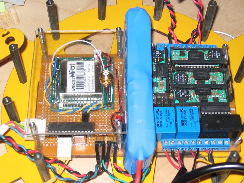
Finally the power distribution board revamp because my current board (on the right) is large, underpowered, and expensive. I think a high current wide input, small footprint board could be developed that would solve everyone’s power problems, not just my own. I am personally of the belief that people trying to do non-static gaits with a biped without a regulated power supply are nuts. They’ll get their timing down for a full charge and the thing will fall over when the battery is partially discharged and the servos aren’t moving as quickly. A high current, reasonably efficient, adjustable regulator is in my opinion absolutely required for any serious attempt at getting these servos to behave in a repeatable fashion.
hopefully you are talking about daisy chaining just your communication wires and not your power distribution, and your I2C has it’s own ground return to the controller.
My plan was to have a 5 lead bus (GND, SDA, SCL, 6V, and 5V). I see the problem of trying to pass all the servos power through little daisy chain connectors and was thinking this would probably be more like 3 busses total (also to keep I2C bus capactiance down and buffer between them).
Why is the common ground a bad thing? Am I passing noise from the motors onto the data lines? I’m not expecting 100% clean data transmission and have built checksums into the OpenServo protocol, but I also would like to avoid any noise that I reasonably can. The OpenServo board itself shares the ground internally (usually shares the 6V too with an internal regulator, but I’m planning on supplying 5V externally). Do you think this is a flaw with the OS design?
A more extensive ground system is always nice, but it’s hard to predict if you will have problems or not. Motors are always noisy, so there is a risk that your I2C will be unhappy sometimes.
Some extra L-C filtering close to the servos may take care of any problems.
You could also consider using small-diameter coax cable for the I2C signals.
You could also reduce the value of the I2C pullups, effectively lowering the impedance of the signal lines (which will increase noise immunity), but you’d need to know that the I2C driver at the other end can handle it.
Another idea: Convert the I2C signals to optical - then they don’t need a ground at all. I guess that would require 3 fibers (clk, data in, data out), and a bit of logic at each end to convert things back to normal.
If you went optical, you might as well use a different protocol, such as Dallas “1-wire”, then you need only (duh) one wire.
Come to think of it, the OS project should probably consider ‘1-wire’ anyway. It has advantages such as only needing (duh) one wire, and you can potentially talk to servos that are not powered up (you can’t move the servo of course, but you could ask it questions). The Hi-Tec ‘HMI’ digital servo protocol is a bit like a 1-wire interface.
Yea, Andy, we all know that you won’t be satisfied unless it’s perfect.
Otherwise, we’ll eventually be hearing that your hexapod that just so happens to be able to do IK cartwheels while doing Calc IV homework needs to be taken appart, because you feel that one optical wire is just so much more perfect than your bus setup.
Besides, you have to be the guiney pig for all of us, so we can bug you about how to do it ourselves.
That’s written in the fine print of your contract.
you know wat kinda is funny though? that even when you finally make it “perfect” in your own sense, and by the time you finish it, you’ll have to take it apart and add to it because it isn’t “perfect” anymore
Everyone has “perfect” in quotes like I said it. I didn’t. Anyone who knows me, especially my wife, knows I’ve never been interested in perfect.
The only reason I started working with robotics was because I wanted a real, textured environment in which to play with AI. Brooks’ situated agents. So far, and as I hoped, the software is proving to be the hardest part of all of this robotics stuff, but the robot itself has been intended to be a tool to achieve that. My current setup seems to have as many obstacles as tools to reaching that goal. And so I start again, armed with a healthy dose of “I wish I knew that last time” but not so much arrogance as to say that this will be the last time I start from scratch.
If you use a star power distribution topology then separate ground for your I2C is a lot less of an issue since you can always return your communications electronics to the same common ground node as the servos.
If you are seriously going to daisy chain servos, which my understanding / experience is some can easily pull 2A in stalled conditions, then you need to consider the effect on the noise threshold of your I2C transceiver (which are probably just port pins on your uC.) What happens is you keep building up small voltage drops at each connection point due to the resistance of the connection and the sum of the current of every servo operating beyond that point. Now your end servo, in trying to assert a low, may be referencing a ground connection that is several hundreds of milivolts above the ground of your I2C tranciever. Add the fact it probably only gets down to 150mV anyway and then consider your typical TTL Vil threshold is only 0.8 volts. A CMOS input will be higher, maybe as much as 1.5 volts. Regardless the point is that if you can not guarantee your signal will be below the Vil threshold of the receiver then there is NO guarantee the low will be recognized. If you consider the total servo current in an actively moving chain of servos can vary widely, this can be a hell of a problem to resolve as it would appear as communication problems and be very intermittent, possibly even depending on which servo in the chain was moving. An input voltage between Vil and Vih is called no mans land because you can read either high or low or worse yet it might be bouncing from high to low and back again. Now if your tranciever has a schmitt trigger type input this helps because you should see right away if you are going to have problems if you test it with all (most) servos in the chain stalled. Better to use a CMOS schmitt trigger so you get the hysteresis plus the higher Vil threshold. Still, taking the daisy chain approach to the extreeme you will eventually reach a point where the tranciever at the controller will not reliably see low going signals. The problem exists at the servo end for the Vih as well but you have a lot more margin to play with there so it may be of less or no practical concern.
If you seperate the logic ground referenced by the I2C signals from the power ground used by the servo amplifier this problem resolves itself. Mind you I am not saying this is “easy” to do because sooner or later your servo controller will have to cross the difference in ground potentials to get to the amplifier. If you are making your bridge from small SOIC Dual FETs and the NFETs have Vg thresholds of 2 or more volts this may not end up being a problem. Last thing is a nagging thought in the back of my head that you may still encounter problems with creating inadvertent ground loops between power and logic grounds but, and this is just a guess, you migh be able to break that with a common mode choke on the power inputs.
On a seperate note, why I2C and not something like the Maxim/Dallas 1-wire or TI HQX single wire protocol? It seems like on the servos you would have plenty of time to bit bang this and at the host end you could either use a dedicated uC / CPLD or protocol specific IC (if you don’t have the time to bit bang it at the host too).
At times like this, I feel like an infant that can’t speak nor understand what he’s hearing, but still listens anyway, because he likes the sound of his parent’s voice.
When you need to connect several things together, a ‘daisy chain’ means going from one, to the next, to the next, etc. It implies that you can’t get to the 2nd one without going through the first one.
Another topology is a ‘multi-tap bus’, where the signal runs nearby, and you tap off of it at various points. But you do not have to pass through any other device.
Another is ‘radial’, where each device has a dedicated line going all the way back to the source.
When it comes to power distribution, radial is perhaps ‘best’, but is the most expensive. Daisy-chain is the worst, because one device can easily affect the signal at other devices.
o0o0o, so is a daisy chain sort of like those suspened metal ball bearings on string, that, when u pick the end one up, the energy of the very first ball bearing gaes all the way through and makes the last ball bearing go?
Thanks for your thoughts… I see your concern about the resistance altering the ground. So my adapted thinking is that I’ll have at most three in series and I’ll add extremely low resistance to my connector requirements. I’ll have to do some more reading about the ground loops to get my head around what I should consider/deal-with there.
As for why I2C? Mostly lack of experience with others. The speeds we’re getting with I2C are pretty nice and at 18+ servos, speed is important. We started to look into CAN but the AVRs with CAN support are unweildy or otherwise inappropriate for the servos and we really don’t have any room on the board for an external tranceiver. I’ll look into the 1-wire protocols. Unless they require other passives in the servo itself and it can be bitbanged, the servos should probably be able to do it with just a firmware change.
Thanks again! I’ll post back when I’ve got something new to report
The Tribotix humaniod utilizes daisy chained servos.
I thought this makes alot of sense, wire management is much simpler, and it looks so clean with fewer wires bundled on the arms and legs.
I wonder if something like that would be possible with the stuff we use?


