AL5D finding xyz position

I currently have an AL5D arm with the SSC-32 controller. I want to use that, and (if necessary) use an arduino uno to have the arm move to an x,y,z position. I was looking at this forum: post-p119738 but this along with the codes was for botboarduino without the SSC-32. Can anyone please help? I eventually want to get the arm to pick up an object placed at a given position.

Thanks in advance!

Hi,

This is a great idea! You can certainly use our newest code examples for the BotBoarduino as a basis for this, too. Of course, some modifications will be required! :slight_smile:
But, luckily for you, this is not as complicated as it may first seem.

The first thing to do is to understand those 3 examples for the BotBoarduino (which is an Arduino-compatible board) and how they work.
In the typical Lynxmotion AL5 robotic arm setup with a BotBoarduino (read more about the AL5 series here), the BotBoarduino is connected directly to the servomotor’s cables (or with extension cables, where needed). This means that the output pins of the BotBoarduino are used to directly control the signal sent to the servomotors. This is done with the Servo library for Arduino.

Of course, in the case of using an SSC-32U to control the servo motors, you will need to change something! That something will either be your wiring or your code (or both :stuck_out_tongue: ).

First, lets check how you can fix this situation by using the same code with some clever re-wiring (read: the lazy/hack method)! As you may already know, the Arduino uses pins 0 & 1 for the hardware serial interface. Therefore, it is common practice to not use this for other hardware. This is why the BotBoarduino connects the servomotor’s signal lines to pins 2,3,4,10,11,12. Since the Arduino board does not have extra connections for the VCC & GND connections of the servomotors (or the extra power supply required), it makes it a bit hard to connect this hardware. Therefore, a simple solution would be to disconnect the servomotors from the SSC-32U and uses jumper wires (male-to-female & male-to-male) to connect the signal portion of the servomotor connector to the proper Arduino pins and the power portion to the SSC-32U (since it has those neat screw terminals for the power connection).

You can determine which pins to use on the Arduino for which servomotor by looking at one of the example code’s definitions, like this one: //Arm Servo pins #define Base_pin 2 #define Shoulder_pin 3 #define Elbow_pin 4 #define Wrist_pin 10 #define Gripper_pin 11 #define WristR_pin 12
On the SSC-32U, these connections start at channel 0 are in the same order, so re-wiring should not be too hard.

Then, program the Arduino with the code meant for the BotBoarduino and this “may work”! Of course, since the robotic is big and may move in unpredictable manner, please make sure to stand clear of it once powered.
Make sure to cut power to the motors (the SSC-32U / AL5 wiring harness) before turning off your Arduino (and while programming it) to prevent erratic or potentially random movements of the robotic arm (from a lack of signal / spurious signals when unpowered but connected to wires).

Now, for the second (proper) method, we will need to go a bit deeper into the code and modify the Arm inverse kinematics function! But, no worries, we don’t need to modify much, actually. Only where the final output is done. Usually, with the BotBoarduino, the output is sent to the servomotor’s signal pins using the Servo library. Instead, in the case of using the SSC-32U to control the robotic arm, you will need to send commands to the SSC-32U instead. you can read all about the commands of the SSC-32U in the manual (page 24-26), available here.

There are two main groups of lines of code that we need to change for this to work.

First, we need to setup a SoftwareSerial interface to the SSC-32U from the Arduino (default baud rate is 9600). This will be done right outside (above) the setup() function and initialized inside it.
The current setup function is like this:

void setup() { Serial.begin(9600); Base.attach(Base_pin); Shldr.attach(Shoulder_pin); Elb.attach(Elbow_pin); Wrist.attach(Wrist_pin); Gripper.attach(Gripper_pin); WristR.attach(WristR_pin); }
First, add a definition for a software serial interface, such as:

SoftwareSerial ssc32u(12, 13); // RX, TX

Then, you can change the setup to be like this:

void setup() { Serial.begin(9600); ssc32u.begin(9600); // Base.attach(Base_pin); // Shldr.attach(Shoulder_pin); // Elb.attach(Elbow_pin); // Wrist.attach(Wrist_pin); // Gripper.attach(Gripper_pin); // WristR.attach(WristR_pin); }
This serial interface (ssc32u) will be used to send serial commands (learn about them from the link to the manual above) to the SSC-32U to move the servomotors around.

The second part of the code that has to be changed is the one from the Arm function that performs the output using the Servo library (which we will no longer use). The code is setup like this by default:

#else Elb.write(180 - Elbow); Shldr.write(Shoulder); #endif Wrist.write(180 - Wris); Base.write(z); WristR.write(wr); #ifndef FSRG Gripper.write(g); #endif
Lets take the Base servomotor as an example. Assuming your base servomotor is connected to channel 0 (as it should be by default) and you would want to place it in the center position, you would simply move it to 1500 us (the RC servomotor center position). This can be done in SSC-32U protocol like this: "#0 P1500**", where stands for a carriage return character (’\r’** in strings in C / Arduino Sketches).
This could be sent like this:

ssc32u.print("#0 P"); ssc32u.print(1500, DEC); ssc32u.print("\r");

In actual code, you would replace 1500 with a variable representing the position of the servo in microseconds.

Since the inverse kinematic function calculates all those positions for the servos in angle instead of a pulse width, you can quickly convert them to microseconds by using the map function, like this:

int servo_us = map(servo_angle, 0, 180, 900, 2100)

We hope this helps you get started with this project! Please don’t be shy to share more details of it here on the forum (especially in the Project Showcase section) or on our project-focused website, Let’s Make Robots!
Also, you can always share new code or fixes/modifications on our Lynxmotion GitHub for this project here. We welcome any code contribution from the RobotShop community!
Sincerely,

I tried the code with the changes you suggested and for some reason it’s not fully working.
I’m wondering, do I do a mapping for every servo like so?

[code]//CONVERT ANGLES TO MICROSECONDS
int elbowServo_us = map(180-Elbow, 0, 180, 900, 2100);
int shoulderServo_us = map(Shoulder, 0, 180, 900, 2100);
int baseServo_us = map(z, 0, 180, 900, 2100);
int wristServo_us = map(180-Wris, 0, 180, 900, 2100);
int gripperServo_us = map(g, 0, 180, 900, 2100);

//WRITE TO SSC-32U
ssc32u.print("#0 P"); ssc32u.print(baseServo_us, DEC); ssc32u.print("\r");
ssc32u.print("#1 P"); ssc32u.print(shoulderServo_us, DEC); ssc32u.print("\r");
ssc32u.print("#2 P"); ssc32u.print(elbowServo_us, DEC); ssc32u.print("\r");
ssc32u.print("#3 P"); ssc32u.print(wristServo_us, DEC); ssc32u.print("\r");
ssc32u.print("#4 P"); ssc32u.print(gripperServo_us, DEC); ssc32u.print("\r");[/code]

Hi,

Yes, you need to do this for every servomotor so that they each get the right signal value from the SSC-32U.

Sincerely,

I am confused as to what I’m doing wrong. I believe I made all the changes you mentioned to the code, but the arm is just stuck in one position once it starts.
If you can enlighten me as to what can be wrong with the code (or if I didn’t make all of the changes appropriately) please let me know.

//#if ARDUINO >= 100
#include “Arduino.h”
//#else
//#include “WProgram.h”
//#end if

#include <Servo.h>
#include <math.h>
#include <SoftwareSerial.h>
//comment to disable the Force Sensitive Resister on the gripper
//#define FSRG

//Select which arm by uncommenting the corresponding line
//#define AL5A
//#define AL5B
#define AL5D

//uncomment for digital servos in the Shoulder and Elbow
//that use a range of 900ms to 2100ms
//#define DIGITAL_RANGE

//define software serial interface
SoftwareSerial ssc32u(12,13); //rx, tx

#ifdef AL5A
const float A = 3.75;
const float B = 4.25;
#elif defined AL5B
const float A = 4.75;
const float B = 5.00;
#elif defined AL5D
const float A = 5.75;
const float B = 7.375;
#endif

//Arm Servo pins
#define Base_pin 2
#define Shoulder_pin 3
#define Elbow_pin 4
#define Wrist_pin 10
#define Gripper_pin 11
#define WristR_pin 12

//Onboard Speaker
#define Speaker_pin 5

//Radians to Degrees constant
const float rtod = 57.295779;

//Arm Speed Variables
float Speed = 1.0;
int sps = 3;

//potentiometer

//Servo Objects
Servo Elb;
Servo Shldr;
Servo Wrist;
Servo Base;
Servo Gripper;
Servo WristR;

//Arm Current Pos
float X = 4;
float Y = 4;
float Z = 90;
int G = 90;
float WA = 0;
int WR = 90;

//Arm temp pos
float tmpx = 4;
float tmpy = 4;
float tmpz = 90;
int tmpg = 90;
int tmpwr = 90;
float tmpwa = 0;

//boolean mode = true;

void setup()
{
Serial.begin(9600);
ssc32u.begin(9600);
/Base.attach(Base_pin);
Shldr.attach(Shoulder_pin);
Elb.attach(Elbow_pin); //not needed
Wrist.attach(Wrist_pin);
Gripper.attach(Gripper_pin);
WristR.attach(WristR_pin);
/

Serial.println("#0 P1500 T500");
Serial.println("#1 P1500 T500");
Serial.println("#2 P2000 T500");
Serial.println("#3 P1500 T500");
Serial.println("#4 P1500 T500");

}

int Arm(float x, float y, float z, int g, float wa, int wr) //Here’s all the Inverse Kinematics to control the arm
{

float M = sqrt((yy)+(xx));
if(M <= 0)
return 1;
float A1 = atan(y/x);
if(x <= 0)
return 1;
float A2 = acos((AA-BB+MM)/((A2)M));
float Elbow = acos((A
A+BB-MM)/((A*2)*B));
float Shoulder = A1 + A2;
Elbow = Elbow * rtod;
Shoulder = Shoulder * rtod;
if((int)Elbow <= 0 || (int)Shoulder <= 0)
return 1;
float Wris = abs(wa - Elbow - Shoulder) - 90;

//CONVERT ANGLES TO MICROSECONDS
int elbowServo_us = map(180-Elbow, 0, 180, 900, 2100);
int shoulderServo_us = map(Shoulder, 0, 180, 900, 2100);
int baseServo_us = map(z, 0, 180, 900, 2100);
int wristServo_us = map(180-Wris, 0, 180, 900, 2100);
int gripperServo_us = map(g, 0, 180, 900, 2100);

//WRITE TO SSC-32U
ssc32u.print("#0 P"); ssc32u.print(baseServo_us, DEC); ssc32u.print("\r");
ssc32u.print("#1 P"); ssc32u.print(shoulderServo_us, DEC); ssc32u.print("\r");
ssc32u.print("#2 P"); ssc32u.print(elbowServo_us, DEC); ssc32u.print("\r");
ssc32u.print("#3 P"); ssc32u.print(wristServo_us, DEC); ssc32u.print("\r");
ssc32u.print("#4 P"); ssc32u.print(gripperServo_us, DEC); ssc32u.print("\r");

int pot = analogRead(A0);
int temp = pot *(1500/1023);
Serial.print("#3 “); Serial.print(“P”); Serial.print(temp); Serial.print(” T500\r");
delay(1000);

/*
#ifdef DIGITAL_RANGE
Elb.writeMicroseconds(map(180 - Elbow, 0, 180, 900, 2100 ));
Shldr.writeMicroseconds(map(Shoulder, 0, 180, 900, 2100));
#else
Elb.write(180 - Elbow);
Shldr.write(Shoulder);
#endif
Wrist.write(180 - Wris);
Base.write(z);
WristR.write(wr);
#ifndef FSRG
Gripper.write(g);
#endif*/
Y = tmpy;
X = tmpx;
Z = tmpz;
WA = tmpwa;
#ifndef FSRG
G = tmpg;
#endif
return 0;
}

// Number of positions to cycle through
const int numPos = 10;

// XYZ position of the gripper in relation to the base & wrist angle
float posListXYZWa][4] =
{
{5,8,90,0},
{8,3,90,0},
{5,5,120,0},
{5,5,90,0},
{5,5,60,0},
{5,10,90,0},
{5,10,90,0},
{5,10,90,0},
{5,10,90,0},
{5,3,90,0}
};

// Gripper closing and wrist rotation
int posListGWr][2] =
{
{90,90},
{90,90},
{90,90},
{90,90},
{90,90},
{90,90},
{0,0},
{120,180},
{0,0},
{90,90}
};

// Delay between moves
long posListDelay] =
{
3000,
2000,
1000,
1000,
3000,
1000,
500,
500,
500,
3000
};
long lastReferenceTime;

void loop()
{

// Example - Follow set of positions
for(int i=0; i<numPos; i++)
{
// Set positions from array
tmpx = posListXYZWa*[0];
tmpy = posListXYZWa*[1];
tmpz = posListXYZWa*[2];
tmpg = posListGWr*[0];
tmpwa = posListXYZWa*[3];
tmpwr = posListGWr*[1];

// Display position
Serial.print("tmpx = “); Serial.print(tmpx, DEC); Serial.print(”\ttmpy = “); Serial.print(tmpy, DEC); Serial.print(”\ttmpz = “); Serial.print(tmpz, DEC); Serial.print(”\ttmpg = “); Serial.print(tmpg, DEC); Serial.print(”\ttmpwa = “); Serial.print(tmpwa, DEC); Serial.print(”\ttmpwr = "); Serial.println(tmpwr, DEC);
Serial.print(“Delay = “); Serial.println(posListDelay*, DEC); Serial.println(””);

// Move arm
Arm(tmpx, tmpy, tmpz, tmpg, tmpwa, tmpwr);

// Pause for the required delay
lastReferenceTime = millis();
while(millis() <= (posListDelay* + lastReferenceTime)){};
}
}********

Please instead attach the code to your post. It makes it easier for us (and anyone, really) to help with it as it is far more readable in a proper editor than in the forum! :slight_smile:

My suspicion is that this isn’t working:

ssc32u.print("#0 P"); ssc32u.print(1500, DEC); ssc32u.print("\r");

When I do a typical line like the following, the arm moves fine:
Serial.println("#0 P1500 T500");

I’m trying to edit this to see if the arm changes in movement but no luck so far.
ssc32u.print("#0 P"); ssc32u.print(1500, DEC); ssc32u.print("\r");
ssc32u.print("#0 P"); ssc32u.print(“1500 T500”); ssc32u.print("\r");

I’m not sure how to attach the code. I’m still relatively new to this forum.

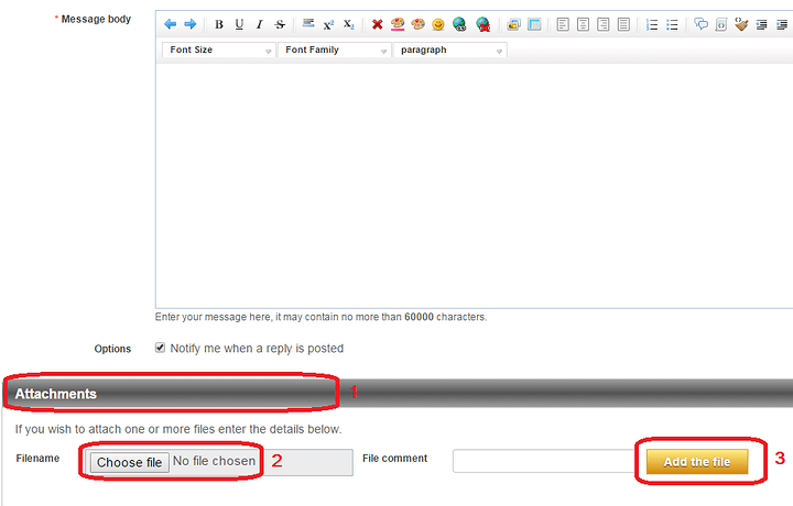
Please see the attached image on how to attach files! :slight_smile:

You have to be in “full editor” for this option to be visible, too.

Here’s the attached code file.
armCodeEdit.ino (5.09 KB)

Any ideas as to what the error could be? I still haven’t been able to figure it out.

We will be looking into this problem a bit more over the holidays, but a good first start would be to double these lines:
ssc32u.print("#0 P"); ssc32u.print(baseServo_us, DEC); ssc32u.print("\r");
with
Serial.print("#0 P"); Serial.print(baseServo_us, DEC); Serial.print("\r");

This way you could see in the serial monitor a debug output of what is being sent to the SSC-32U.

The code is finally working! However, I am trying to understand the kinematics. From the looks of it, a polar coordinate system is being used.
In the following code

float M = sqrt((y*y)+(x*x));
 if(M <= 0)
   return 1;
 float A1 = atan(y/x);
 if(x <= 0)
   return 1;
 float A2 = acos((A*A-B*B+M*M)/((A*2)*M));
 float Elbow = acos((A*A+B*B-M*M)/((A*2)*B));
 float Shoulder = A1 + A2;
 Elbow = Elbow * rtod;
 Shoulder = Shoulder * rtod;
 if((int)Elbow <= 0 || (int)Shoulder <= 0)
   return 1;
 float Wris = abs(wa - Elbow - Shoulder) - 90;

what I understand so far is that variable M is basically r in the 2-dimensional polar coordinate. Whereas float A1 would be theta thus Polar: (r,theta). I do not understand the rest however. I do see that the arm’s dimensions (constants A and B) are being used in the rest of the computations. Is there any way you can explain this part of the code a bit further?
armCode.ino (6.02 KB)

Hi,

We are glad to know the code now works for you. What was changed (in the code or physical setup) / what was the issue you fixed?

Concerning the inverse kinematics, since they are done in 2D the calculations are all done using basic trigonometry.
The values of M & A1 relate to the position of the gripper relative to the base / X-Axis. That’s the easy part! :slight_smile:

Then, we need to figure the two main servomotors, the shoulder and elbow. This is done using the Law of Cosines (specific article), an extension of the Pythagorean theorem that applies to any triangles. By playing around with the formula you can determine any angle from the lengths. Since we have all 3 lengths (M being the one that varies), this tells us which angles we need for the servomotors at each joints.

Here is a quick and dirty way to view it:
Starting from COS C_deg = (a² + b² - c²) / (2ab) => C_deg = ACOS(a² + b² - c²) / (2ab)], we will get the measure of the angle opposite whichever side is placed as “-c²”.
Following this logic, A2 = ACOS(A² - B² + M²) / (2AM)] is giving us the angle of the shoulder servomotor (inside the triangle), since it is on the opposite side of the B side (the should-to-wrist piece).
Similarly, Elbow = ACOS(A²+B²-M²)/(2AB)] is giving us the angle of the elbow servomotor (inside the triangle).
At the end, the angle of the shoulder is corrected to be relative to the X-axis (X plane / the table or ground) by combining the values of A1 & A2.

Then, the values are converted from radians to degrees by multiplying by a constant (~180/Pi), rtod.

Finally, if all the values seems ok, the Wrist angle is corrected so that everything looks good.

We hope that helps!

Sincerely,

The physical setup and code didn’t really change. The only thing I deleted from the code was the additional softwareSerial variable and instead just used the standard arduino serial pins so that the command will simply be Serial.println(…).

That was a great explanation! I really appreciate it! There is still one thing I don’t quite understand however, and that is why A1 and A2 are added to correct the shoulder angle relative to the x-axis. I’m trying to understand why that part works. Is there a theorem/law explaining it? I just don’t get why adding both of the angle values will result in the appropriate angle.

Hi,

The A2 angle is the angle inside the triangle. Like the one for elbow, they tell us how the arm should be placed in relation to itself. But, the arm is a physical object in the real world, and we need a reference to the base (and the plane holding it). Therefore, we also need the angle A1, which is the angle of the side M with respect to the X-axis (or the ground plane the robot arm is resting on). This tells us how the robotic arm should be place in the world, where as the A2 and Elbow angles tell us how the arm is positioned related to the shoulder joint / base.

Please have a look at the attachment and see if it helps a bit.

Sincerely,