

Intro:
I always used to connect my arduino to my macbook for power. However, I needed to disconnect it from the computer for use on a robot I'm working on. Because I didn't have any of the jacks that would fit in the arduino, I decided to solder a 9v battery snap to the bottom of the board. Here's how I did it.
You will need:
- An Arduino board (Full size ones only, pro mini, etc. won't work)
- 9v battery snap
- Soldering iron
- Solder
Optional but highly recommended (adding a diode):
- Heat shrink tubing (I used 1/8 in. and 1/4 in. diameters)
- Wire cutters/strippers
- Hair Dryer or similar (to melt the heat shrink tubing)
- Diode (I used the 1N4005)
Step 1 - Load a Sketch:
Load up a simple sketch to the arduino. I like the blink sketch that everybody starts with. It is in Examples > Digital > Blink. During the course of the project I used the blink sketch to test whether power was going to the board. Because Adruinos have a built in LED, I didn't even need to add any components!
Step 2 - Solder it up:
Once you've got all your materials gathered, you need to solder the 9v snap to the arduino. The best way I found to do this is to melt a little bit of extra solder onto the pad. Let it cool and then melt all of the solder that is now on the pad. Then place the battery clip lead into the molten solder. Let it cool and repeat. You can do this any way you want, though.

Step 3 - Test That Sucker:
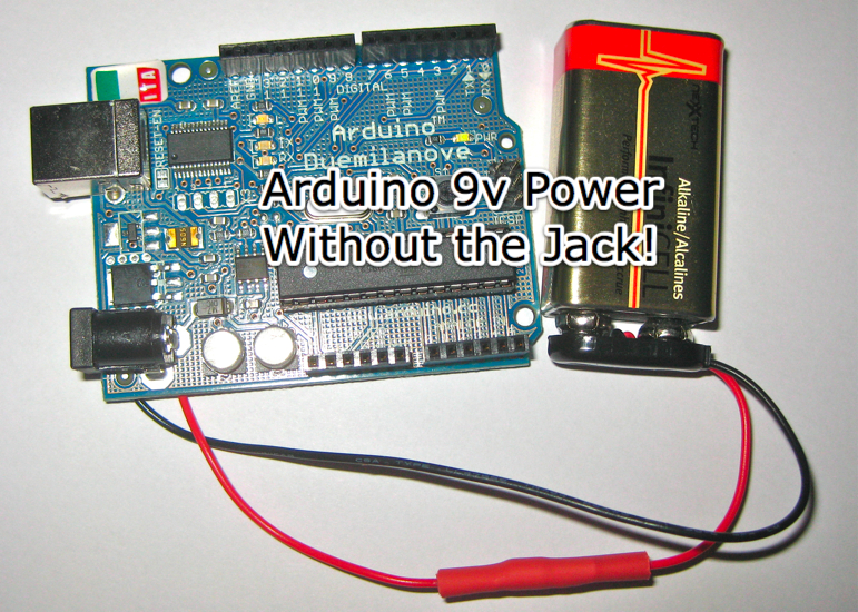
Clip a nine volt battery to the clip. Watch that you don't accidentally touch the battery to the contacts the wrong way, as this may brick your whole Arduino. This is why we will add a diode in the next few steps. The LED on pin 13 should start blinking if everything is working.
Here's what it should look like.

You’re done but…
If you are making the basic version without the protection diode you are ready to roll. However, I highly recommend adding the diode so that you can’t destroy your Arduino by accidentally touching the 9v battery to the contacts wrong.
Step 4 - But Wait! There’s More:
The first thing you need to do to add the diode is to cut the positive (red) lead of the battery snap. I cut mine around the middle. Strip a bit of insulation off of the ends of the freshly cut wires. In an effort to make my positive and negative leads the same length, a cut a bit less than a centimetre off of one of the wires. This will make it roughly the same length as the negative wire once we add the diode!

Step 5 - Heat Shrink:
Now is the opportune time to add some heat shrink to the wires since you can't after you solder in the diode. I added a 1/8 inch diameter piece to each of the leads. My pieces were about 2 cm long. Lastly, I added a longer 1/4 inch diameter piece on the longest lead. The small tubes provide stress relief for either side of the diode. The large piece prevents shorts from anything still sticking out. I will shrink it over the whole diode/heat shrink setup to make it look nice. Don't Shrink the Tubes Yet!
Step 6 - Twist the Diode in:
Now you need to add the diode. I twisted the exposed wire around the leads on either side of the diode. Make sure you don't put the diode in the wrong way! You need the stripe to face the direction the current is flowing (towards the arduino). Maybe a photograph could describe this better.

Step 7 - Solder it in:
Before you solder, check that all of the heat shrink is on the wires. This is because you'd need to desolder the diode to put it on if you forget. Now you can solder the connections between the battery clip and the diode. Just solder where you twisted the battery clip wires to the diode leads. Solder close to the diode to minimize the size of the whole thing. When you're done, cut off the unused diode leads. They aren't needed anymore.

Step 8 - Heat Shrinking:
Get a hair dryer from somewhere and shrink the heat shrink tubing. Its probably not wise to use a heat gun or soldering iron as that may damage the diode. I shrunk the two smaller diameter pieces around the diode and solder connections. When that was done I shrunk the larger diameter tube over both of the small ones to make it look more finished.
Project Done!
Well that's another project finished! I hope you guys enjoyed this little tutorial. If you have any questions, put them in the comments because I'd love to help! One last note is that you may want to use some hot glue as strain relief on the battery clip leads where they connect to the Arduino. Mine are looking a little weak already.
