The idea is balance a platform in a dynamic equilibrium with the two servos, as on if it rotates clockwise (0 to 90 degrees) in the x axis, it would move servo a in the positive direction, and servo b in the negative direction.
likewise on the same x axis if the platform rotated counterclockwise, servo a would move in the negative direction, and servo b would move in the positive direction.
Also there will be movement in the y axis(0 to 90 degrees). In a manner such that if the board starts to rotate forward servos a AND b will both move in the positive direction, and if it starts to rotate backward, servos a AND b will both move in the negative direction.
Will the microcontrolled be able to accept those signals and send out the proper balance to each servo? (As in there will movement in x and y axis at the same time, which will mean each servo has two inputs)
For example if movement in the x axis tells servo a to rotate 30degrees clockwise, but movement in the y axis tells it to move 15 degrees counterclockwise, will the end result be a rotation of 15 degrees clockwise like I need it to be?
sld be ok, but i tink instead of having 2 inputs for 1 servo, u can try combining the 2 values (value = Servo1 + Servo2) and sent out the result to the servo. Of course, this is not fool proof, u’ll need to make sure it stay within the min and max range.
My experience with the parallax accelerometer was that these devices are very sensitive, so if connected to the servos, it might result in jittering.
Thank you thats a good idea, as for the accelerometer, as an optional replacement I was looking at this one http://www.dimensionengineering.com/DE-ACCM6G.htm, have you had any experience with it/will it still work in conjunction with the microcontroller?
As for sensitivity, very little is required. As the object will rotate up to a max of 90 degrees (through normally will only be around 45) in each direction.
In fact due to how much vibration the object will encounter, I was thinking some sort of delay should be programmed into the microcontroller as to help eliminate jittering. As I am just trying to compensate for excessive roll, not tiny vibrations.
can all this be programmed into the arduino opensource programming that they offer? Which I believe is similar to C?
On a side note would these components be assembled on just a standard pc board like the ones at radioshack. Also, what is a good way to ground out the microcontroller?
Just assembled as in mechanically attaching the microcontroller and accelerometer to a board, that will then be attached to the platform.
As for power source, would just a standard 9v work with that microcontroller?
Also concerning power the accelerometer I am looking at said “There is no on-board regulation, provided power should be between 1.8 and 3.6VDC.” I am assuming the accelerometer will get its power from the microcontroller, but how do you control how much power the microcontroller will supply to the accelerometer?
I don’t want to be negitive here but it seems by some of your questions, you might be biting off more than you can chew here. I wish you the best of luck with this project, but you might want to start a bit smaller or break this up into smaller steps. Also, you might want to read some of the data sheets that come with your products.
I say this as a friend… There are a few “rules” around here --People will not react well if you are asking a question that is easily found in a manual. I.e. the fact that the microcontroller board you are looking at has a 3v out or that almost everything connected to anything must share a ground. Also, and this might be a personal pet-peeve, don’t ask questions about step 487 when you have not figured out step 1,2 and 3.
What you are trying to do is possible. It’s as simple as reading the inputs, writing an algorthm that will do the calculations that you need, then outputing those values to the servo. What you should do is write down the order that you will do things then translate it to code. Example
get input from Accerometer
translate x/y input value to servo motion
do math on servo values from x/y servo motion
send servo command.
go to step 1.
The Arduino or picaxe could do this. The Ardunio uses libraries that are written in C. Whatever you write will be C if you use an arduino.
A 9v batter will fry everything without some sort of regulation. Get a 5v regulator (or 3 if you decide to go that route). Also the MCU will NOT power the accelerometer but it can use the same power line that the MCU uses if it uses the same voltage(which you said it does not, see next line)
As far as the accerlerometer, i would find one that is 5v. If not, you will need to get an additional 3.3v vreg for the accelmeter. You will also end up using the vref so that they arduino can use the 3.3v correctly.see http://arduino.cc/en/Reference/AnalogReference
You could attach the accel to a simple pcb board that they sell at Rshack. I would suggest getting a breadboard though and testing your ciricut on that.
“The ACCM-3D has an onboard 3.3V LDO regulator, allowing you to power the board with 3.5V to 15V sources. You can also use this regulator to power an external microcontroller with up to 50mA. For operation as low as 2.0V, you can bypass the voltage regulator and choose your own operating voltage.”
So i am thinking i can run this off of a 9-volt, and power the microcontroller from this board? As for the two servos (http://www.servocity.com/html/s3003_servo_standard.html) i plan on powering those also from the 9-volt also but using a regulater to drop it down to 6 volts before it gets to the servos.
Can all this be run off of a single battery? Also if anybody has a schematic laying around i would love to see it, haven’t really been able to find one and any help would be greatly appreciated.
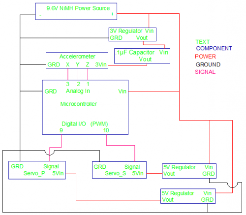
Hey Guys here is a schematic I made for this system. As you can tell my electrical sense is not the best. If anybody can take a look over it and point out any mistakes or improvements. I would really appreciate it.
First issue and costly one, you are running 9.6v into your uProc. Instant fry…or close to it. second, you have 2 vregs, you only need one. Third, I would recommend running a 7.2v pack, use one 5v vreg that could power the 2 servos and uProc, then use a 3.3v reg running from the 5v reg to power the 3.3v powered sensor. for the 3.3v sensor to the uproc remember to use the analogue ref pin.
No major flaw, but you could save weight by using a smaller 3.7v lip rated at the same Mah and about 1/4th the size.
You could also use a stepup converter like this for the servo, but this is pretty low mah output that would only work on 1 servo I’d guess(check cuurrent draw stats on the servo you are looking at using).