I recently purchased a Lynxmotion autonomous A4WD rugged wheeled rover my thesis project , and i finding it difficult to write the motor encoders to the botboarduino . I have a background in aerospace engineering structures so wiring and electronics are still alittle new to me. Is there anyone who can help me figure that out and also help me with understanding how to initiate providing a code to the botboarduino to cause motion of the rover? I have the Arduino environment downloaded and tried it myself but the motors would not spin.
I connected the 4 encoders of the 4 motors to the pins on the far right side of the botboarduino. The motor controller provides power to the botboarduino but I’m not sure how to reference those pins in the code. I searched and other people used the PWM pins at the top but I’m not sure if those are used are connected to those??
Once you have that working you can try using the encoders. The botboarduino doesn’t have enough dedicated interrupt pins (you need 8 inputs, 2 for each enconder), however, if you want to use them (using an extra microcontroller or an expansion board) this example may come in handy:
Where the A & B channels (of each encoder) should be connected to interrupt pins.
Additional info:
The botboarduino also supports “pin change interrupts” that allow you to detect a change in state (high to low or low to high) on a larger set of pins compared to the dedicated i In the ATmega328, there are three Pin Change Interrupt vectors (PCINT0, PCINT1, and PCINT2) that correspond to three groups of pins:
PCINT0 corresponds to digital pins 8 to 13 on the Arduino Uno.
PCINT1 corresponds to analog input pins A0 to A5 on the Arduino Uno.
PCINT2 corresponds to digital pins 0 to 7 on the Arduino Uno.
So in theory it could be possible but challenging because of the computational overhead of handling so many interrupts.
Hello, thank you for your response and assistance!
I did as you instructed with the set up and tried out the code to turn the motor, and uploaded the code into Arduino but the TX, RX and Red LED lights turned on with a buzzing sound but no rotation in motors. The error light also came on onto the Sabertooth board, I believe the code was unable to be uploaded onto botboarduino, achieving this error code:
Sketch uses 3016 bytes (9%) of program storage space. Maximum is 30720 bytes.
Global variables use 236 bytes (11%) of dynamic memory, leaving 1812 bytes for local variables. Maximum is 2048 bytes.
avrdude: stk500_recv(): programmer is not responding
avrdude: stk500_getsync() attempt 1 of 10: not in sync: resp=0xd7
avrdude: stk500_recv(): programmer is not responding
avrdude: stk500_getsync() attempt 2 of 10: not in sync: resp=0xd7
avrdude: stk500_recv(): programmer is not responding
avrdude: stk500_getsync() attempt 3 of 10: not in sync: resp=0xd7
avrdude: stk500_recv(): programmer is not responding
avrdude: stk500_getsync() attempt 4 of 10: not in sync: resp=0xd7
avrdude: stk500_recv(): programmer is not responding
avrdude: stk500_getsync() attempt 5 of 10: not in sync: resp=0xd7
avrdude: stk500_recv(): programmer is not responding
avrdude: stk500_getsync() attempt 6 of 10: not in sync: resp=0xd7
avrdude: stk500_recv(): programmer is not responding
avrdude: stk500_getsync() attempt 7 of 10: not in sync: resp=0xd7
avrdude: stk500_recv(): programmer is not responding
avrdude: stk500_getsync() attempt 8 of 10: not in sync: resp=0xd7
avrdude: stk500_recv(): programmer is not responding
avrdude: stk500_getsync() attempt 9 of 10: not in sync: resp=0xd7
avrdude: stk500_recv(): programmer is not responding
avrdude: stk500_getsync() attempt 10 of 10: not in sync: resp=0xd7
Failed uploading: uploading error: exit status 1
I set up the Arduino Environment to be “Arduino Duemilanove or Diecimila” with the Processor being “ATmega328P” as these were the closest options to what was suggested in the manual.
Do you know what could be causing this upload error?
As you mentioned, one of the problems is that you weren’t able to upload the code to the botboarduino so let’s try to upload a simpler code.
Disconnect everything from the botboarduino (except the USB cable of course), on the Arduino IDE go to:
File > Example > Basics > Blink
Choose your board “Arduino Duemilanove or Diecimila” and the COM port.
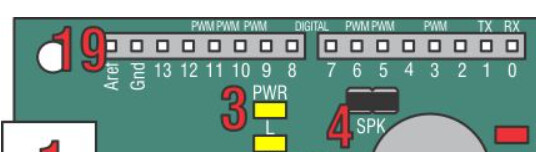
Once uploaded the LED “L” (under the power LED) will start blinking.
If this doesn’t work please check how the jumpers are placed
If everything seems correct check the following troubleshooting steps:
Hardware Checks:
Check the USB Cable: Sometimes the issue is as simple as a faulty or loose USB cable. Try using a different cable to see if the issue is resolved.
Check the COM Port: Ensure that you’ve selected the correct COM port in the Arduino IDE.
Check the Drivers: Make sure that the necessary drivers for the Arduino board are installed on your computer.
Software Checks:
Arduino IDE Version: Sometimes an outdated IDE can cause issues. Make sure you’re using the latest version of the Arduino IDE.
Firewall/Antivirus: Sometimes, security software can block the necessary ports. Disable your firewall and antivirus software temporarily to see if that resolves the issue.
Upload Settings: Check that you’ve chosen the correct settings for “Programmer” under Tools > Programmer.
Restart the IDE: Sometimes simply restarting the Arduino IDE or your computer can resolve the issue.
Serial Monitor: Make sure the Serial Monitor is closed before you upload, as it can interfere with the uploading process.
I did as you asked and restarted my computer. I was able to upload the code and the LED PWR and D4 lights came on with the buzzing sound, but no motors were turning. Is this supposed to happen? I was looking at the code and it mentioned keyboard letters. I set the baud rate to 115200 as mentioned in the code and tried sending some commands through serial monitor but nothing happened the the motors stayed still. I tested out the motors to ensure they were not faulty and they all spun individually so i am not sure what could be wrong. Kindly help, and thank you so much for your help through this process
I was looking at the code and it mentioned keyboard letters. I set the baud rate to 115200 as mentioned in the code and tried sending some commands through serial monitor
Oops forgot to give instructions for the code but you figured it out! That’s exactly what you are supossed to do
Do you get any error LED lights on the sabertooth?
Attached is the photo of how I connected the Sabertooth to the botboarduino. I also uploaded a video of what i see with the power is connected, with the lights and buzzing sound.
I Initially thought the buzzing sound was because I made a connection at Pin 5 with S2 from the sabertooth but even after i completely removed that connection, the buzzing sound was still there and the red D4 light was still on. I looked online and it mentioned this symbolizes a reset in the board so when I send the “W” and “S” instructions through Serial Monitor, nothing gets processed and it is immediately erased. I tried pressing the reset button on the botboarduino but the D4 button momentarily disappears and reappears again. I t
hought something was wrong with the board so I used the simple blink code you suggested and TX blinked intermittently which shows the board works. Is my wiring the problem? Is it the code? I tried changing the baud code to 2400 to see if any change would be prominent but nothing works and I am at lost for words…
It looks like you have wires connected to the screw terminals and also the red wire coming from the Sabertooth (the middle red one feeds 5V) - could it be you’re providing power from two competing sources? The BotBoarduino doesn’t need a VL (9V).
The wires connected to the screw terminals on the Botboarduino are not providing any power since I did not connect them to a battery source. I actually removed them right after taking that photo just to see if it has any effect but I still got the same feedback as shown in the video and I am not sure what could be wrong (video shows the red and black wires removed from the screw terminals on the botboarduino). Could it be the code I was presented? I tried the simple blinking code on Arduino and that worked fine with no buzzing so I’m very confused
You have the jumper for the speaker/buzzer on (which is connected to pin 5 which is used in the code), please remove that jumper or switch pin 5 to another one that supports PWM (and update the code accordingly)
I removed the jumper for the speaker and the sound went off! The red LED light on D4 still lights up as red, Is that supposed to happen? The Sabertooth board does not seem to have any errors since the error light is off. I also try inputting commands into the serial monitor of my arduino environment but it does not seem to be processed since nothing shows up in the monitor once I hit enter. I tried “W” + Enter but nothing goes through. I looked online on the manual and I found out that the D4 LED turns red since its connected to pin 7, which is called in the sample code you provided initially. I am still not sure why nothing is being processed in my arduino environment and the motors are still not working. Are the rest of my connections accurate? Is my selection of “Arduino Duemilanove or Decilima”, then choosing ATmega328P under “Processor” accurate?
I am so sorry for the many questions. I just have a tight deadline for my masters project and the first part is getting the rover running and nothing seems to work :(.
Thank you so much for your time and effort in assisting me with this.
The red LED light on D4 still lights up as red, Is that supposed to happen?
No, but it is probably because of the pin 7 conflict. I updated the code please use the latest one. I tested it with an oscilloscope and I got the correct PWM signals when I pressed the keys.
It is a bit hard to tell with so many cables of the same color, but at first glance, it seems correct. Regarding the DIP switches it is also hard to tell because of the resolution but they look correct as well. However, please re-check this just in case:
Is my selection of “Arduino Duemilanove or Decilima”, then choosing ATmega328P under “Processor” accurate?
Yes
Also, if the Blink LED code worked it means there is nothing wrong with the Arduino, the problem was likely caused by the pin conflict. If not, then it is likely a connection issue, please make sure your cables are not broken, that the DIP switches are correct, and that you have enough battery.