

This is my first attiny project after getting an led to blink. I guess it's a little ambitious - I hadn't even cracked the datasheet when I started. For my plan I needed to get PWM working, figure out how to take ADC readings, and figure out something to do with an extra pin. Here are the main parts I used (USB adapter thing for scale):
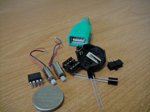
I've got a bunch of attiny85s, sockets, batteries, and battery holders. I only have the two pager motors (scavanged from misc. things), but I have an order in for some geared pager motors. I don't know if I have any more of the light sensors around either, but I can probably make due. I plan on making at least one more of these tiny bots!
I'm using an Arduino setup as an AVR ISP:
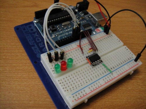
I ordered and assembled a programmer from AdaFruit. I didn't get around to testing it out until this morning though... and then OSX said it disabled it because "a device was drawing more power then it should"... even without the power jumper in! Oops! Well, The Arduino ISP works really well!
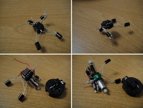
I did a bunch of reading, read a few chapters of the datasheet forward and backward. I made several tests, building up the pieces I needed - first getting PWM working with timer1, then getting readings from a sensor (and using PWM output on the motor to see the reading). Finally I breadboarded all the parts to see if I could get it all running:
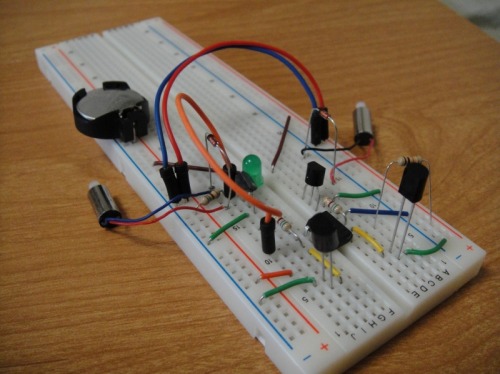
(oops, can't see the MCU in that shot)
No surprise, but it turns out one CR2032 can't power the MCU, an LED, and both motors. Luckily its easy to add an extra power supply to just the motors - I just moved both positive leads to one trace, then connected a battery between that trace and ground. Here is something like the motor "driver" I'm using.
I also added an LED to my leftover pin (PB0). The only interesting thing that pin can do by itself is output PWM using timer0, so I decided to make the LED pulse to show that the MCU is running. I had some problems getting a fade though, all I could get was some flickering. I also had some problems getting both light sensors working... I think I should have tested them with an Arduino where I could have printed the readings to serial...
So I decided to freeform the whole robot around the dip socket. Freeforming is so open ended, I had some problems deciding how to route power and mount the motors. It turned out okay though.
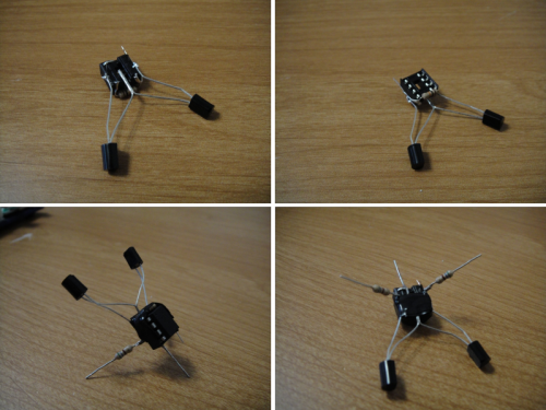
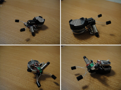
Disaster! Even though I double checked and labeled the motors so when I wired them they turned the right way... So of course the left motor turns the wrong way! I also can't tell if the sensors are having an effect... I've run out of weekend though. Hopefully I can get things sorted during the week and get some video to post!
Lives on a table, reacts to light
- Actuators / output devices: pager motor
- CPU: attiny85
- Power source: CR2032
- Programming language: C (AVR GCC)
- Sensors / input devices: reverse biased ir emitters
- Target environment: tables, desks
This is a companion discussion topic for the original entry at https://community.robotshop.com/robots/show/a-tiny-bot
