A week ago I had the idea of building another lab supply. MetalmonkeeLad (Keith) suggested sharing it with the LMR lot so here we go.
To keep it simple I kept the specs pretty low, but still I wanted a bipolar supply to power opamps.
The voltage can be adjusted from 1.25V to 11.6V (-1.25V to -11.6V for the negative rail) and the maximum current for both rails together is 1A.
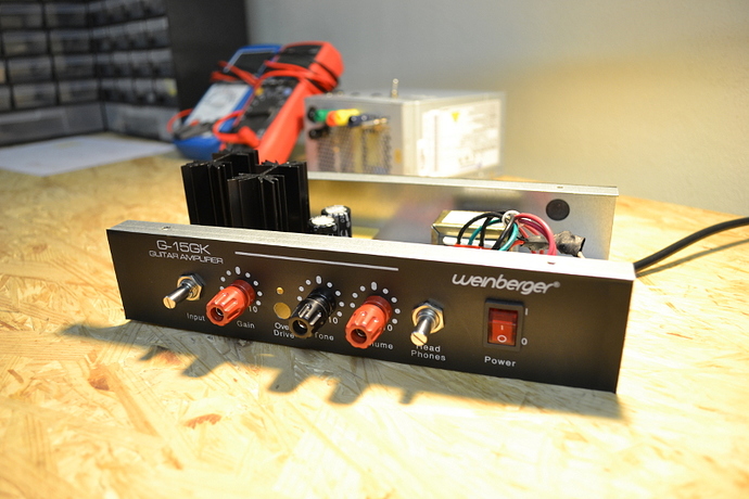
Though the goal was to make this thing pretty small I ended up taking apart a cheap guitar amp that I didn't use anymore.
The guitar amp provided me with a 2x 12.9V transformer and a nice case to use. The amp is rated at 15W meaning that I can get about 15W/12V = 1.25A out, which tranlates to 625mA from each coil, 550mA to have a little safety margin.
The Schematic:
click for a bigger image!
C1 and C5 are the smoothing caps for the 16V output from the bridge rectifier. C2, C3, C6, and C7 are just to prevent both regulators from oscillating.
R1 and R3 esnure that there is a minimum load on the regulators to keep them stable and R2 and R4 are 1k 10 turn pots to adjust the voltage. C4 and C8 are the output capacitors.
D2 and D3 prevent the output capacitors from discharging through the regulator and thereby damaging them. D4 and D5 prevent the regulators from damaging eachother if one of the regulators powers up faster than the other.
I know the video lacks a bit of information but together with this post it's okay.
Tell me what you think :)
If you like the video or post give me a thumbs up on YouTube or leave a comment on my blog. You free to comment here aswell of course :)
https://www.youtube.com/watch?v=VbhXawTwPhU


