Hey everybody. I am a long time lurker on this site and I would like to thank you all for all the valuable information here. I have built a start here bot and a few more complex things of my own. Now I am trying to build a very small sized robot with a picaxe 08m.
I am a beginner in electronics. I know how to hook up a LDR and read the input, but I would like to know if there is a possibilty to hook up 2 to 1 input. The problem is I am short 1 input on my robot and all the other picaxe pins are in use. The 2 ldrs would be used as left and right eyes in a sense.
So, is there any simple schematic to hook up 2 ldrs in a fashion that would make it possible to read comparative data from it?
For instance that the adc input 0 or something else low would mean the left sensor sees more light, a middle reading of 127 would mean they are the same and 255 would mean the right sensor sees something brigther.
THanks all who bother to answer. Il hopefully be posting my micro scale robot on christmas :)
I would assume and maybe others can confirm, you could make a resistor bridge with them. --Two sensors, each with 2 legs. Connect one wire each (from each sensor) together. This conection will go to an ADC input. With the remaining 2 pins, 5v+ will go to one and ground to the other. That’s it. I have never done this but in theory, it should work.
Here is your test code:
main:
readadc pin,b0
debug
goto main
Now shine your flashlight on each sensor and note the numbers. --Should work.
Like I said I am a beginner at this stuff, but what you said actually sounds pretty logical. I have to wait about 5 days til I get the LDRs to confirm though.
I’ve used this arrangement on several projects with great success - one of the advantages of this design is that it is almost immune to ambient light interference, since both sides of the bridge will be offset. The relationship between relative left/right light intensity and output voltage is a bit awkward, but in most cases you only need to fuzzy logic at best so calibration is fairly easy.
It depends on the exact behaviour you want, but in most cases the easiest way to handle the sensor data is something along the lines of: • Read [ADC in]. • If 110 <= [ADC in] <= 145, then [light position] = in the middle. • If [ADC in] < 110, then [light position] = to the left. • If 145 < [ADC in], then [light position] = to the right.
You can break the light position bands down into further smaller groups, just remember that the band from 100 - 120 won’t cover the same light angle as 120 - 140 for example. This sensor setup is typically much more sensitive around the mid-point than it is towards the far left or right, so I definitely suggest using a dead-band around the middle instead of just 127 = [ADC in], then [light position] = in the middle, especially if you’re going to try to track/lock onto the light source.
Oh, and naturally you’ll get the best results if you use identical LDRs, from the same batch if possible =)
When using “unpredictable” resistors like LDRs in a voltage divider, you never know how much current is going to flow through the whole circuit at any time. Unless you add some fixed resistors. See these examples.
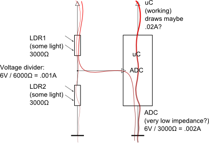
Scenario 1: This is the voltage divider Chris is describing under moderate light conditions. The LDRs I am using myself give an average resistance of a few kilo Ohm when moderately lit. Let’s assume a V+ of 6 V. Watch the current flowing through the two LDRs.
That's reasonable: 1 mA flowing through. You battery will sustain that for a long time. Compare the current your micro Controller is probably drawing at the same time.
I do not know how much the resistance (impedance) of your ADC port is, but let's consider the worst case scenario. The impedance is pretty low compared to the resistance in your LDRs. That will make your readings unreliable AND your ADC is going to draw a current of its own. The resistance in LDR1 is the only thing preventing a short circuit through your uC.
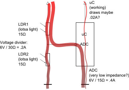
Scenario 2: When lots of light hits the LDRs, the resistance is almost nothing. Let's assume 15 Ohm.
There are two problems now: the divider is drawing a whopping 200 mA from your battery. But worse than that: the current flowing through the ADC is even higher! (This is not really what happens. The main current is either flowing to ground through LDR2 or through the ADC. Not both. It depends on the unknown impedance as compared to the resistance of LDR2.)
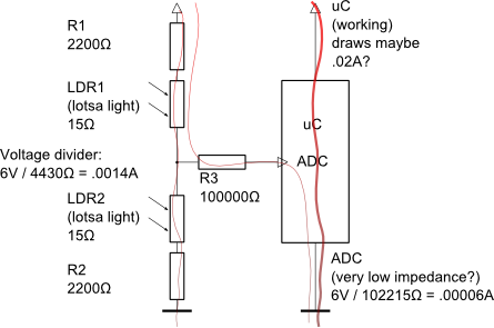
Scenario 3: The current through the divider must be limited by one or two fixed resistors. The current into the ADC can be restricted by one fixed resistor.
The values to use depend on the actual resistance in your LDRs. R1 and R2 need to be comparable to the resistance of LDR1 and LDR2 under average light conditions. Experiment with those. I am assuming 2200 Ohm is good here.
The value of R3 can be quite high. There is absolutely no need for any current to flow into the ADC. This example uses 100 kilo Ohm. I used 1 Mega Ohm with good results on a Picaxe 40X2.
To summarize: you don't need strong currents through your voltage divider, but you need some current. Anything between 1 mA and 1 uA will do. Use a measuring thingey to find the true current drawn by your entire circuit.
Wow. Thanks for the great schematics and explanation! Regretfully I don’t have a “measuring thingey” though. I will probably soon have to buy one of those too. I quess I’l have to just go find/scavenge/buy some resistors and start experimenting with the different values.
I already ordered all the rest of the parts I still needed. I hope to repay all this great help you are giving people here for free by sharing a few tricks of my own soon. I will just have to get this robot finished first, then I can post how I built it. I’ve so far searched around on this site a lot and I havent seen any robot as small as mine is going to be yet. Right now I am aiming for slightly smaller than a matchbox with about as much functionality as the start here bot.
Man, rik… You nailed that answer, rik. Damn good. I never thought about what would happen when they went down to that low of a restance. I guess at some point you would almost have two straight wires short-circuiting themselves right out. (I know LDR’s can’t get to 0 ohms). At any rate, much respect for that answer.
Yes, rik makes a very good Yes, rik makes a very good point. I’m used to very high resistance LDRs and high impedance micro inputs, so I tend to forget about these things =) Just to reinforce what rik said near the end, make sure there is at least 1μA current through the LDR voltage divider, otherwise the circuit becomes susceptible to static/EMF/other sources of noise.