6 wire RC steering servo?

Hi All!

This is my first post so go easy on me. :)

I am trying to build an obstical avoidance robot and decide to salvage a chasis from an old Radio Shack RC truck. The main board is fried. when I got to the se=teering mechanism I discovered 6 wires coming form what I would think is a servo. I was expecting three wires so I'm not sure how to hook it up to my motor shield for an arduino.

I discovered that if I applied a voltage to two of the wires the wheels turn on direction and if I reverse them they go the other way.

I was thinking of just treating it like a dc motor but didn't think I could get the best accuracy and when the steering direction maxes out in either direction i'm affraid I might burn it out.

I am open to any suggestions.

Thanks so much

Bean

Another guess.

I would agree with BDK, Although I don’t know much about it and is a long shot, if there isn’t a motor driver board in that box with the steering motor, the wires MAY have something to do with the digital proportional steering found in “higher end” RCs. I’d put a multimeter on two and see if you can get a switch to close by moving the steering to one side or the other before cracking that open. (probably contains a myriad of gearing). Let us know what you find.


EDIT:

I dug around a bit and found this:

http://www.rcgroups.com/forums/showthread.php?t=1475741

Seems the servo driver is on the main board and those are the leads from the pot for proportional steering control.

Maybe you cound check the resistance of two that aren’t powering the DC motor and see if the resistance changes as you move the steering of the wheels by hand to confirm.

A reaction to A guess and another guess

That’s a great idea guys

I hope that there is some kind of indication of maximum steering direction. I would love to be able to use that feedback.

I will definately give this a try tomorrow.

I will keep you all updated.

Bean

How I got mine to work:

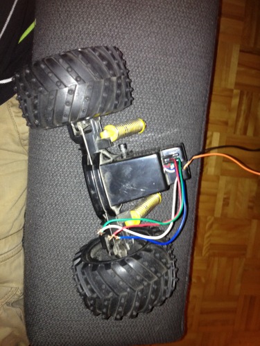
I have two of those exact same dc motor/ sensor combos, and I have found how to work them. Here is an picture of the internals of the unit:

1_279.jpg

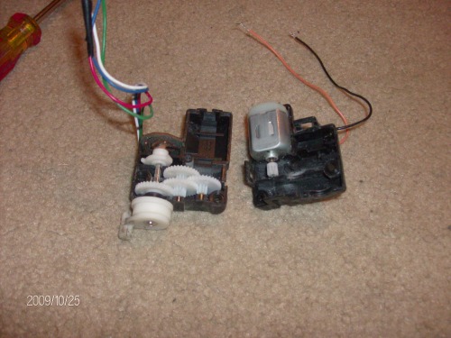
Note that the black and brown wires connect directly to the DC motor inside (as you have obviously found out yourself) and the remaining 4 wires run to a very interesting position sensing device. It only senses when the wheels are full left, full right, and centreing from either side, Now, I took apart my unit in hopes of using the internals to figure out how the sensor worked, but I found it didnt really help, I got more confused than helped from looking at it, What I found was the best way to determine how it worked was use the motor (a nine volt battery works nicely here) to power the wheels full left, and try every possible combination of wires using a multimeter, and write down which pairs gave me infinate resistance, and which ones gave me close to 0, repeat except full right this time, and finally, using some aligator clips, find which ones give you zero ohms as you go from left to right and back again (they will be different pairs for going different directions) There is absolutely no rhyme or reason to how the wires are connected up, and when one pair reads zero ohms, for one position, chances are it wont even connect to the other one. The way I planned to do it, was have each of the wires connected thru a resistor to a GPIO pin, and using the table I generated when I wanted to move the wheels to a position (left, right, middle from left, or middle from right) I would bring one of the pins high, send a signal to the motor to start turning, and stop it when the pin that indicates when the motor has got there shows voltage. I think it has to be done that way because of the way the swich is made, so it is a little labour intensive, but I think it will be cool when I get it working.

If all of that seems like a lot of work, I discovered that if you use the green and red wire as a switch and wire it accordingly, it will sense when you have centred the wheels. but only from one of the directions, I cant remember which, and the gear train has enought "hold" that if you send it a short (half second or so) burst of power, it will move to one of the sides, and stay there. To get it centered again from either of the sides, if it is the side that it senses from, its easy, just tell the motor to turn untill the switch activates. To get it to centre from the other side is a bit trickeyer, and clumsyer, but it still works fine. Send it a shot of power, enough to make it turn further than centre to the other side (I used .7 seconds) and then tell the motor to turn back again, just like you did for the other side. It sounds really long and awkward, but in real life it doesnt take much time at all. I actually built a robot that used a lego NXT as the brains, with the steering motor hooked up to a motor port, and the red and green wires hooked up to a sensor port acting like a touch sensor, that used that exact logic. I made subrutines for "left" "right"  "centre from left" and "centre from right" which made the rest of the programing easier. Unfortunatly, didnt care much about documenting my builds at that time, and never took any pictures or videos aside from the one up there. The downside to this method is you dont get any outside feeback limits, only feedback for centreing the wheels.


Hope that helps, and wasnt too convoluted :)

Excellent help!

That is great help!

I Think I will try out the pot with series resister to GPIO technique when I have a chance.

Just to confirm your method though, you applied a voltage to one side of the pot and depending on the voltage at the output, you signaled the motor to go or stop based on a tested list of tabled results. Is this correct? 

Bean

Thanks :slight_smile:

Ok, first things first, The feedback sensor isnt a Potentiomiter, it is a strange sort of switch that makes use of only 4 wires to give you 4 different position feedback results, and as such, requires some pre-planning, hence the table, but, yes your basic idea is right. You need the resistors to prevent any chance of a short, but yeah, you feed voltage into one of the wires (make the pin an output, and set it to high) (like if you are centreing from the side that uses the red/green wire pair, feed voltage into the red one) start the motor turning in the direction you want, and tell it to stop when you see voltage on the pin hooked up to the green wire (which you set up as an input shortly before you started this process) the wire pairs will change for every different limit you are looking for (left, right, centre from left, centre from right) which is why you need to have to have each wire connected to its own pin, and change the input/output statuses before you make any move. again, Table is really handy here. I recconmend subrutines for each of the states, which will make it much easier to code the rest of the code.

Once again, I hope this helps instead of confusing you more.

I’ve got some work ahead.

This is definately more a help than confusing. Thank you sooo much.

My experience with LMR so far has been great, and extreamly helpful!

The dificult part will be creating this table. Time for a little reverse engineering I guess.

I will keep the forum updated on my findings, but I’m really excited to solve this puzzle. I will need to do some power requirements research to get things up and running too. So I’m sure my second post will be somewhere along those lines lol.

Bean

Just in case anyone still cares…

Not sure if Bean has already figured this out already, but I just thought I would post for completeness, and in case anyone else stumbles upon this thread. I found the table of wire connections that I made earlier, here are the results with the colours being the wire pairs that should be used like switches that will close when the action you want is completed.

Red & Green: Center turning right (it differs depending on the direction that the wheels are turning)

Blue & Red: Center turning left

White & Green: Full left

White & Blue: Full right

I planned to use a seperate microcontroler to handle all of the messy coding for the feedback system and motor control and just have two control lines running to it, bring one high, and the chassis turns left, the other one high and it turns right.

1 Like

HELP

Hi, I’m new to the forum and do not write very well English, I’m from Spain and I have a problem with a servo 6 cables, need to know if I can move from this servo and inject one standard or simply if someone can help me rebuild (basically the part of the board) should switch gears because they are worn, I send photos and hope you can help me because I see that there are great professionals here;)


IMG_20160115_150436.jpg