How I got mine to work:
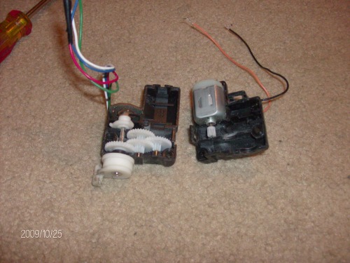
I have two of those exact same dc motor/ sensor combos, and I have found how to work them. Here is an picture of the internals of the unit:

Note that the black and brown wires connect directly to the DC motor inside (as you have obviously found out yourself) and the remaining 4 wires run to a very interesting position sensing device. It only senses when the wheels are full left, full right, and centreing from either side, Now, I took apart my unit in hopes of using the internals to figure out how the sensor worked, but I found it didnt really help, I got more confused than helped from looking at it, What I found was the best way to determine how it worked was use the motor (a nine volt battery works nicely here) to power the wheels full left, and try every possible combination of wires using a multimeter, and write down which pairs gave me infinate resistance, and which ones gave me close to 0, repeat except full right this time, and finally, using some aligator clips, find which ones give you zero ohms as you go from left to right and back again (they will be different pairs for going different directions) There is absolutely no rhyme or reason to how the wires are connected up, and when one pair reads zero ohms, for one position, chances are it wont even connect to the other one. The way I planned to do it, was have each of the wires connected thru a resistor to a GPIO pin, and using the table I generated when I wanted to move the wheels to a position (left, right, middle from left, or middle from right) I would bring one of the pins high, send a signal to the motor to start turning, and stop it when the pin that indicates when the motor has got there shows voltage. I think it has to be done that way because of the way the swich is made, so it is a little labour intensive, but I think it will be cool when I get it working.
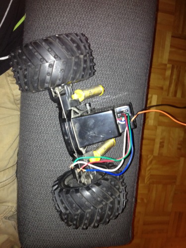
If all of that seems like a lot of work, I discovered that if you use the green and red wire as a switch and wire it accordingly, it will sense when you have centred the wheels. but only from one of the directions, I cant remember which, and the gear train has enought "hold" that if you send it a short (half second or so) burst of power, it will move to one of the sides, and stay there. To get it centered again from either of the sides, if it is the side that it senses from, its easy, just tell the motor to turn untill the switch activates. To get it to centre from the other side is a bit trickeyer, and clumsyer, but it still works fine. Send it a shot of power, enough to make it turn further than centre to the other side (I used .7 seconds) and then tell the motor to turn back again, just like you did for the other side. It sounds really long and awkward, but in real life it doesnt take much time at all. I actually built a robot that used a lego NXT as the brains, with the steering motor hooked up to a motor port, and the red and green wires hooked up to a sensor port acting like a touch sensor, that used that exact logic. I made subrutines for "left" "right" "centre from left" and "centre from right" which made the rest of the programing easier. Unfortunatly, didnt care much about documenting my builds at that time, and never took any pictures or videos aside from the one up there. The downside to this method is you dont get any outside feeback limits, only feedback for centreing the wheels.
Hope that helps, and wasnt too convoluted :)


