Hi!
I’m having a problem with a omni-wheeled kit. I have assembled it and installed the test code that runs the demoActions function. On the first action, the bot works fine, but on every subsequent action, motor #1 runs at full speed in the correct direction, regardless of the speed setting in the software.
I have access to a second kit of the same model, and have installed the same code on it. It works fine, with no sign of this issue. This leads me to believe it is a hardware problem, specifically in either the motor controller or the encoders on that wheel. I had initially thought that the encoder lines for that motor being in a different location may have been responsible. According to my multimeter, each of the other motors’ encoders is getting 5VDC whereas the problem motor is getting about 4.6 V. But, this would not explain the motor working correctly on the first command in the demo function. It seems that the setCarSpeedMMPS function will temporarily fix the speed, until the next direction change.
Without a pin schematic available for the microcontroller, motor shield, or motors, I cannot check the power connections to the shield or motors with a multimeter.
Thank you so much!
Hello @qfrederick and welcome to the community!
I’m sorry to hear you are having issues with the kit 
As you said the fact that everything works with a second kit of the same model probably means that the issue is, in fact, a hardware problem, either something with the motor, the encoder or the connections. Seeing that you have the possibility to check the connections yourself I think that schematics of the parts of the kit will come in handy.
The microcontroller is the Arduino 328 and the expansion board is the IO Expansion Shield in those link you will find the schematics. In the ZIP file provided in the product page of the Omni Wheel Arduino Robot you can find a diagram with the connections and a manual that shows the pinout of the boards and the configurations.
I hope that information can help you out, but if you still aren’t able to find what the problem is please let us know 
Thank you @geraldinebc15 ,
I had found the constituent items and the included documentation, but I’m glad for the confirmation I was looking at the right items :). I see the electrical schematics of the terminals, but I was hoping for a physical schematic (perhaps I should have said board file) to associate named terminals with the unlabeled pins on the boards.
I believe these are the schematics/diagrams you are referring to. Is there any documentation that details the function of each pin, not just the groups of pins?
After more testing, I am experiencing another issue. When changing direction, the bot will ‘jump’ in the new direction–as if an impulse input were given to the motor controllers. Could this be related to the wheel issue? Each is related to the controller.
Hi again
Yes, I was referring to those but also to the schematics available in the useful links of the product pages I mentioned, the microcontroller and the expansion shield.
Regarding the new issue, I’m not sure I understand exactly what happens. Do you mind sending a video of the problem? Also, a picture of the motor wiring would be helpful!
As you suggest it could be either a problem with the motor, the encoder or the microcontroller, have you tried switching the position (and wiring) of two motors, if the problem persists in the same motor it would definitely mean that something is wrong with it.
Thanks–
As I said, I’m afraid these schematics are not helpful without a way of telling where the terminals are physically located on the board.
I did try switching two sets of encoder cables, but as I could not switch the power connection to any motors (this would void any return policy), it just set up an open loop, with the microcontroller expecting feedback from one motor and getting it from the other, and so was not helpful. However, I did edit the setup software to initialize the problem motor as a different one, and the problem remained on the same motor.
The wiring is just as it was out of the box:
I’ll try to get a video posted soon.
I have narrowed the problem down to the encoders on the one motor. It looks like the amplitude on one line is at about twice that on the other. Would the amplitude affect perceived encoder count?
Hi again,
Sorry for taking long to reply, I wasn’t able to check the schematics before and as you said they aren’t very helpful. I found some discrepancies between what the manual from the manufacturer says and the schematics like this:
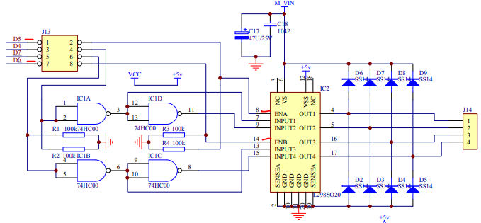
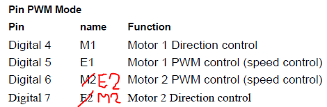
But that could just be a typo and means we shouldn’t rely entirely on the manual 
What I find a bit strange is the position of the enable in the pictures you sent, could you check the voltage on those pins? I’m not sure where it is connected because, as you said, there isn’t much information about the board. Also, could you send more pictures of the setting? Showing the whole board and maybe the ones from the kit that is functioning?
I wasn’t able to see the video, maybe you could upload it to youtube and share the link here 
I’m pretty certain the enable is fine–I am not certain which terminal/jumper the enable is, but the jumper configuration is identical to that of the functional kit. Here is a photo of the functional bot’ motor controller:
And the non-functioning one:
I don’t know if you saw my other post, but I am pretty certain there is some issue with the one motor’s encoder. The signal on one of the lines displays an unusually high amplitude.
Here is the video:
https://youtu.be/S1c-JO8GUIM
Hello again, sorry I missed that post!
The encoder might be altering the motor’s control signal. This motor seems to have an incremental encoder of two channels, these are used mainly to determine the direction of rotation. The signal of each channel is a square wave with a 90º offset between them. When you tell me that one of the channels has approximately twice the voltage of the other, it could mean that the channel is always at a high logic level, meaning there is a problem because both should have the same amplitude, as consecuence the system won’t detect the direction of the rotation and therefore for that direction the error of the control system would be incorrect, saturating the system and accelerating the wheel to the maximum, which seems to be what is happening to you.
If you say that in both robots everything is connected the same way, the problem could be a broken cable or if the corresponding connector is defective or loose, you could check that by testing continuity. If that is not the case the encoder is probably in bad condition. As the encoder is used for the feedback of the control system you could try to manipulate that wheel without the PID control by changing the code, in case that works it would definitely mean that the problem is the encoder.
1 Like
Your assessment makes a lot of sense. A broken/railed out feedback path would result in exactly the error I’m seeing, except for the first direction in the routine…is there any way an encoder channel would change state when direction is reversed? Perhaps a short between the direction line/encoder output?
I doubt a connection is physically broken, as this would mean the motor would never work correctly. That consistent phenomenon of correct operation on the first part of the demo script is puzzling.
When the direction of the motor is reversed the encoder channel signals will change, the leading signal will now be the delayed one and viceversa, but the amplitude of the signals should be the same, you can read more about how rotary encoders work here.
Do you have access to an oscilloscope? The troubleshooting would be much easier if you could actually see the signals from the encoder channels. If you do, you could follow this guide to help you troubleshoot.
I’m afraid I do not have an o-scope. I am starting to think I will look into getting the problem motor/encoder replaced unless another option presents itself. Thank you for all your advice!
1 Like


