First of all, I want to thank all of you guys who's robot projects and blog entries make this site such an amazing place! You all ignited my passion for robotics! I've dedicated my life to computers and programming and this is a really cool way of connecting it with the real world :-)
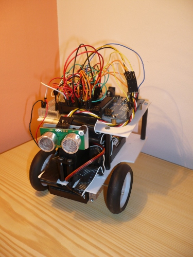
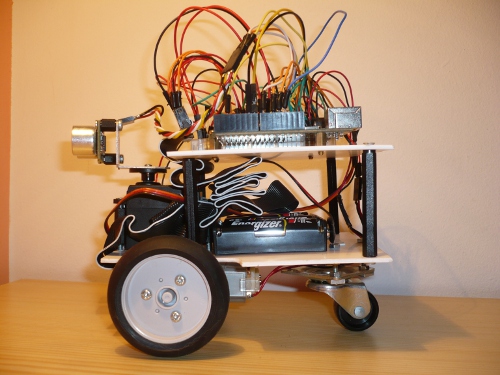
This is my very first robot called 2Deckard and is far from done but I really feel like sharing my first steps :-) The robot is driven by Arduino Uno, it has 2x 3V DC motors controlled by SN754410 IC (in combination with one 74HC04 hex invertor IC), two TM70145 wheels and one TM70168 gearbox form Tamiya, and SRF05 distance sensor attached on servo. There is also an IR detector that will be used to switch robot modes by TV remote control (right now I've got some problems with detecting signals from remote, I've made it work when the motors are disconnected but as soon as I plug them in I'm recieving a lot of noise... but since there is just one mode at the moment it doesn't bother me so much :-) ).
As a power source I use one 9V battery (for Arduino, servo and sensor) and 4x AAA alcaline battery (for motors). I'm planning to switch to rechargable batteries because the alcaline ones are drained pretty fast (especially the 9V one).
Right now it's just a prototype with lots of wires hanging from solderless board :-) One of the planned improvement is to create custom PCB that would be used as an Arduino shield (I know there is a lot of similar projects on the web but I would like to try making my own version).
So far the robot is moving around the room and avoiding obstacles. It seems that it's "navigating" quite well and it made it's way out even from a dead end of room. I have in plan to add line following (such a popular "hello world" of robotics :-) ) and maybe some other cool stuff, like aiming a poisoned darts throwing cannon :-) For a line following I'll use QRD1114 attach to the PATA cable that is taped to a gearbox on the front (one of many nice ideas I saw while wandering on LMR :-) ). One pair of QRD1114's will maybe end up as wheel encoders. There is so much more I would like to improve, still there is 6 analog inputs and 7 digital I/O left :-)
You probably already know this, but adding some small capacitors on the motors will remove lot of the noise.
Take two capacitors and twist them together.
Scratch a spot on the motor between the two terminals. Using soldering iron apply some solder. Then solder the twisted end of the two capacitors to the spot on the motor case.
Take the other end of the twisted pair of capacitors and insert one end to each motor brush terminal.
Place a third capacitor between each motor brush terminal.
Thank you, Geir! I found a lot of design flaws when constructing the chasis but it’s a first version and still it was fun making it
Thanks for advice about filtering the motor noise! I often saw a capacitor between motor terminals but was never sure why is it there (and now I know ). I am still a beginner with electronics (forgot pretty much from what I’ve learned back in school). I will try to put three caps on each of my motor tomorrow. Do you think 0.1uF ones will do the trick?
Hey Geir, that is an interesting link. Have you ever tried using shielded cable and the ferrite rings on your motors in addition to the capacitors? Looks a bit extreme, but I’m sure that it might be worth it for some applications.
Another technique I have used is to twist the motor leads. This makes a twisted pair, which in theory should reduce noise. I have never done any testing to see if it is effective, since I don’t own an oscilloscope.
I’m planning to switch to 9V NiMH 200mAH rechargable battery, or maybe for some NiMH battery pack. It would be nice to have one battery source for both the logic and the motors.
From what I know the Arduino has it’s own 5V power regulator, so it should be all right to use 7.2 or 9V NiMH battery and connect it right to Arduino and (through some power diodes or voltage divider) to DC motors.
I’m thinking about switching the original 3V DC motors that came with Tamiya gearbox with some low current 6V ones, because the original motors take 2.1A (per motor) when stall, which is quite a lot.
So today I’ve finally found some time to progress with my little project. I soldered 2x 0.1uF caps to each motor (each from terminal to body) but I found out, that the IR detector is recieving noise even when only the servo is moving… So it looks like the IR is pretty sensitive to any kind of noise.
Noise can come from many sourcdes, including your power supply, motors, servos. It is always best to try to eliminate or reduce the noise as close as possible to the source.