

OBJECTIVE
The point of all this is to empower the already powerful wiimote. Without any modding the wii can already talk to a computer using a variety of libraries (wiiuse for C, wiiusej for Java)
But there is not much ability for the computer to talk back to the wii.
In order to turn your wiimote into a powerful robot - you will want a micro-controller connected to it.
Now, I want my computer to talk back and forth to the micro-controller. How do you do this?
Well, there is the possibility of the microcontroller to pretend its a wii extension , but again this is one sided. The uC can talk to the computer, but the computer can't talk to the uC.
If you solder the buttons & LEDs to the uC this might allow another form of communication.
The computer can turn the LEDs on and off on the wii which will be transmitted to the uC. And the uC can control the buttons on the wii which will be transmitted to the computer.
Sooooooo, in rapid succession turning on and off buttons and leds will make serial communications between the uC and the computer !
Many possibilities could come out of this. For example, SLAM is very data/processing intensive, especially visualizing the Mapping. At the moment it would be very difficult for a uC to create 3D maps, however, the computer can do this. So, the WiiBot travels on the floor transmitting position and range info to the computer, and the computer transmits movement controls back to the WiiBot...SWEET !
SERIAL DETAILS
This blog will be the search for 2 way wireless communication to a WiiMote using the button pads and LEDs.
If this is completed communication will be established like the following
Computer <----serial over bluetooth through buttons & LEDs-----> wii-mote <-->Arduino.
Which might be able to provide framework for remote wireless bots & other fun projects.
So Far I have connectivity both ways, and even the beginnings of full serial connectivity... but there are parts still missing.
Details coming...
As a reference this is one of the best diagrams I found on the web for what Arduino wants is a serial packet. Commonly referred to as 8N1 - found here
The period of the start bit lasts this long for the following baud rates (I think)
9600 = 0.000104167 pause
2400 = 0.000416667 pause
1200 = 0.000833333 pause
300 = 0.003333333 pause
So, the Java code on the computer side looks like this
int period = 4; // this would be 2400 baud
// beginning of start bit
lineDriver.pulseDown();
Thread.sleep(period);
// end start bitStringBuffer s = new StringBuffer(8); // for logging (the binary string)
// 8 random bits
for (int i = 0; i < 8; ++i)
{
int x = generator.nextInt(100);
if ( i < 9) //&& i < 7 //x > 150 &&
{
lineDriver.pulseUp();
s.append(“0”);
} else {
lineDriver.pulseDown();
s.append(“1”);
}
Thread.sleep(period);
}// the stop bit
lineDriver.pulseUp();
Thread.sleep(80); // extra time just to be nice
Experiment 1
Yarg! The “inverted” did not work, in fact it “feels” like it should be the other way.
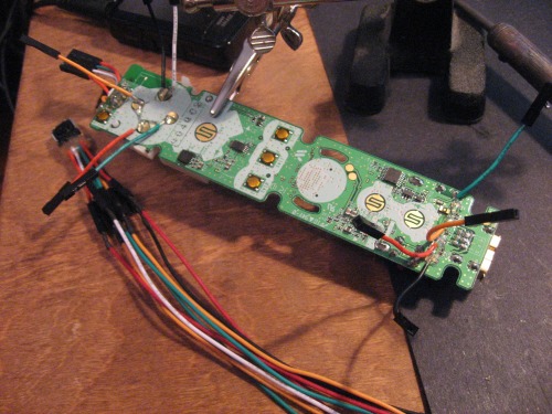
The hookup looks like this :

LED 4 on the wiimote is hooked to pin 2 on an Arduino
The Arduino code looks like this:
Which just tries to read the serial LED from the wii and prints it out on the monitor.
#include #define rxPin 2 #define txPin 3 #define ledPin 13boolean ledState = false;
int counter = 255; // To slow down the LED blinking
byte incomingByte = 0;NewSoftSerial nss(rxPin, txPin);
void setup() // run once, when the sketch starts
{
Serial.begin(9600);
nss.begin(2400);
pinMode(ledPin, OUTPUT); // sets the digital pin as output
digitalWrite(ledPin,ledState);
delay(2000);
}void loop()
{if (counter > 0) {
counter-=1;
} else {
ledState = ! ledState;
digitalWrite(ledPin,ledState);
counter=255;
}if (nss.available() > 0) {
incomingByte = nss.read();
//Serial.print(incomingByte);
Serial.print(incomingByte,HEX);
nss.print(incomingByte);
// Serial.write(incomingByte);
}delay(1);
}
Output

Unfortunately there seems to be occasional data when the data in, is all 0's and just 0's when the data is all 1's.. so I think the inverted thing is a red herring.
The good part is 1 number is getting written out for 1 number written in... that's a little encouraging...
I'll flip it back and start trying different baud rates...
Experiment 2
By Jove, I think I'm close ! I set the serial input on the Arduino at 300 -> nss.begin(300);
And left the period = 4 in the Java code and look !
The following is the serial monitor where a bunch of 1's was written then a bunch of 0's..
Its great, because it looks like its framed correctly, even though the data is inverted.... occasional garbage appears hmmm..
So I think I was 1/2 off with the period... at least.. and maybe a fraction more with the little garbage...

Now to invert the logic and attempt to stabilize it.
Yarg ! - can't seem to clean it completely... I assume it has to do with delays on the computer side, but have not completely convinced myself. Tried much longer spans of time between sending bytes.... did not seem to help.
The 0's are really solid, but the 1's lose the LSB occasionally... I think that would correspond to a computer delay...not sure
Any serial guru's out there?

UPDATE - 5/31/2011
After attempting to bit-bang it and use other techniques to get stable serial information, I gave up and tried using parallel.
Strive to Fail !
And the serial stuff was definitely a failure, not only was it crappy rate (< 150 bps) - but even at the slowest it wascompletely unstable.
Next I looked into the possibilities of parallel communication. Parallel ports on computers use a "strobe" pin as a means to synchronize peripherals. To use this synchronization meant I would only get to use 3 leds for data and 1 for strobe.
In addition is a wii initialization issue. The wii when initially connecting with bluetooth flashes the dang leds on and off. So I wrote some Arduino code which knew how to disregard this garbage and look for a magic byte to initialize and re-assemble bytes from the 3 bit parallel / serial protocol.
Now with some experiments I get a ~1.5 Kbps data stream that is flawless !
Dead Wii !
At this point I have fried the wii, because I was impatient and hooked the Arduino's 5v to it. In retrospect this was completely stupid. I could have solved the voltage problem just by tapping off 2 of the 4 AA batteries driving the Arduino. If someone (birdmun?) had the gumption, they could put together a really impressive & inexpensive little bot ($16 Arduino $25 Wii - pocket laser - couple of motors or continuous servos). It could have WiiDar and roll around mapping everything for your computer wirelessly.
Holy Mac - writing this make me want to do it !
As promised here is the Arduino code (or specifically - the guts which deal with the parallel communication)
In setup - it just setting the pins to INPUT
  if (serialCommType == WIICOM)
  {
    pinMode(LED1, INPUT);
    pinMode(LED2, INPUT);
    pinMode(LED3, INPUT);
    pinMode(LED4, INPUT);
  } else if (serialCommType == VIRTUAL_WIRE)
I have a getCommand routines which uses a 3 byte protocol -
there is an if statement which can easily change the form
of serial communication
boolean getCommand ()
{
if (serialCommType == WIICOM){
if (strobeState != digitalRead(LED1))
{
// strobed - data ready
strobeState = digitalRead(LED1);newByte <<= 1;
newByte = newByte + digitalRead(LED2);
newByte <<= 1;
newByte = newByte + digitalRead(LED3);
if (nibbleCount < 2)
{
newByte <<= 1;
newByte = newByte + digitalRead(LED4);
}
++nibbleCount;/ must comment out debugging - if using serial for control /
Serial.print(nibbleCount);
Serial.print("-");
Serial.print(newByte, HEX);
Serial.print("\n");// the wiimote flashes its led when first searching for a connection
// this can be a little problematic - so we take care of it here
if (!readySteady)
{
if (newByte == 0x00 || newByte == 0x07)
{
nibbleCount=0;
newByte = 0;
//Serial.print(“disregarding\n”);
return false;
} else {
Serial.print(“first nibble\n”);
readySteady = true;
}
}
if (nibbleCount > 2)
{
nibbleCount = 0;
ioCommand[byteCount] = newByte;
++byteCount;
newByte = 0;
/ must comment out debugging - if using serial for control /
Serial.print(newByte, HEX);
Serial.print("|");
Serial.print("bc ");
Serial.print(byteCount);
if (byteCount > 2)
{
return true;
}
} // if nibbleCount > 2
} // if strobeState
} else if (serialCommType == VIRTUAL_WIRE) …
The full pde file can be found here http://code.google.com/p/myrobotlab/source/browse/trunk/src/resource/arduinoSerial.pde
The Java code which talks to it can be found here
http://code.google.com/p/myrobotlab/source/browse/trunk/src/org/myrobotlab/service/Wii.java

