Using a Dot Matrix LCD With a Microcontroller

LCD displays are a great way to add output to your robot - they can be a very useful debugging aid and also can make controlling the robot much easier (setting options, viewing battery voltage etc.).
One main drawback is that they require up to 10 IO lines to use (although this can be reduced to 6 - see below). Serial controllers are available, but I will discuss how to control the displays using a parallel bus.
The display I am using is made by Trident but uses a standard instruction set. These instructions are for the Hitachi (HD44780) chipset, which is a common standard. A cheap display can be had for around £7 ($10), but add a few pounds (or dollars) for a backlight.
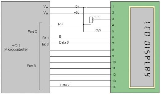
As I mentioned, the display can be used with either 6 or 10 output lines. If the display is set to 8 bit operation (where the data bus contains 8 connections between the display and controller) or 4 bit operation. In 4 bit mode, the code for each instruction or character must be sent in 2 parts; the first 4 bits (the most significant bits) and then the second 4 bits. As well as the data lines, there are 3 control lines; E, RS and RW (Enable, Register Select and Read/Write). For most operations, the Read/Write line can simply be tied to 0v.
Unfortunately, I have only had experience using the display in 8 bit mode so this is what I will discuss in this article. However, the Hitachi datasheet details how to use the 4 bit mode.
The code in this article is written in Motorola HC11 assembly (although I actually developed in on the HC05), but can easily be modified for any microcontroller.
Initializing the Display
Before data can be sent, the display must be set up. This is done by sending a series of commands, and between each, 'strobing' (turning on then off) the Enable pin (E). Below is a routine to send the relevant codes to the display setting it up with the most common settings.
The code assumes the 8 data lines are connected to port B (output-only port) and RS and E are connected to bits 0 and 1 of port C.
SetupLCD
ldaa #$ff
staa ddrc ; Set port C as an output portldaa #$01 ; Clear screen
jsr ctrllong ; Need longer wait for these commands
ldaa #$02 ; Home cursor
jsr ctrllong
ldaa #$38 ; Set data bus width, no. of lines, font size
jsr lcdctrl
ldaa #$0c ; Turn on display, no cursor
jsr lcdctrl
ldaa #$06 ; Set entry mode (see text)
jsr lcdctrl ; LCD now set up
rts
The 'ctrllong' and 'lcdctrl' subroutines simply strobe
the Enable line and pause for a while to let the display execute the
instruction. Below is the code for this;
lcdctrl
stab tempb ; Save registers
staa tempa
staa portb ; Put data onto port B
bset 1,portc ; Strobe 'E line
bclr 1,portc
jsr wait120us ; Wait a while
ldaa tempa ; Restore registers
ldab tempb
rtsctrllong
stab tempb ; Save registers
staa tempa
staa portb ; Put data onto port B
bset 1,portc ; Strobe 'E' line
bclr 1,portc
jsr wait5ms ; Wait 5ms
ldaa tempa ; restore registers
ldx tempb
rts
First of all, the contents of the 'a' and 'b' registers are stored in temporary variables and the data is stored at port B. The 'E' line is then strobed (bset and bclr stand for bit set and bit clear). Below are the pause routines (these depend on the clock frequency however).
wait5ms
ldaa #3 ; Change this value depending on clock frequency (assumes 4MHz crystal)
outer
ldab #$ff
inner decb
bne inner
deca
bne outer
rtswait120us
ldab #30
loop120
decb
bne loop120
rts
Note: The timing of these delay routines is not critical; as long as the delays are longer than 5 milliseconds and 120 microseconds respectively, they should work fine.
Now that the display is set up, the rest is easy! The display accepts characters in standard ASCII format, so the 8 bit code for a particular character is placed in the 'a' accumulator and another routine is executed. This time, the 'Register Select' line must be set to a '1' first, to tell the display that we are sending data rather than an instruction.
To send the letter 'A' to the display for example, the following code is used.That's just about it - this code lets you set up the display and enter any character you want (There is a full character set on the Hitachi data sheet - this is an invaluable resource!). There are many more function however; You can create your own characters, read data from the display (this needs the R/W line though), and set the way in which data is entered onto the screen. However, I hope this tutorial has given you a basic knowledge of these very useful displays.ldaa #'A' ; Print an 'A'
jsr lcddata
here bra here ; Stop!lcddata
stab tempb ; Save registers
staa tempa
staa portb ; Put data onto port B
bset 0,portc ; Set 'RS' line to '1'
bset 1,portc ; Strobe 'E' line
bclr 1,portc
bclr 0,portc ; Clear 'RS' line
jsr wait120us ; Wait 120 us
ldaa tempa ; restore registers
ldx tempb
rts
There is a very useful FAQ on the Hitachi chipset at http://www.cen.uiuc.edu/~cburian/lcd.doc.
Disclaimer
Sorry I have to include one of these, but I make no guarantee that the above code will work perfectly. As I mentioned, I have only tried the code on an HC05 microcontroller. If you would like a copy of this, feel free to mail me at [email protected].
Angus Thomson, 2000
Thanks for helping to keep our community civil!
This post is an advertisement, or vandalism. It is not useful or relevant to the current topic.
You flagged this as spam. Undo flag.Flag Post


