Raspberry Pi Free Style Powering

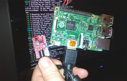
This tutorial enables you to power your Raspberry PI II / B+ / ZERO/ 3 from any power sources that supplies voltage between 6.5V up to 20V and current >1A.
For this how to, I used as power source the 19V wall power adapter from one old BENQ notebook.
This hack is useful, also, in configuration where gel-Lead(Pb) rechargeable batteries are used as power supply.
Time needed: between 15 to 30 minutes.
Skills required: soldering.
Gathering all parts and tools together
Parts:- 1pcs. x g-SPS 5V version switching power supply
- 1pcs. x 2.1mm/2.5mm barrel power jack (choose one that fits with your wall adapter) or see the "Barrel jack alternative" and g-SPS reference later
- 1pcs. x 3 pins standard 0.1"/2.54mm row-header 90 degrees or straight + connecting wires x2
- optional 1000uF/6.3V electrolytic capacitor, low ESR (optional, useful in case of high current consumption pulses)
- about g-SPS 5V version [PN. gSPS102#5V(LiPOL)]
- Raspberry PI 2 / Raspberry PI B+ / Raspberry PI ZERO extension pin out
- soldering iron
- small pliers / clip
Soldering the connectors
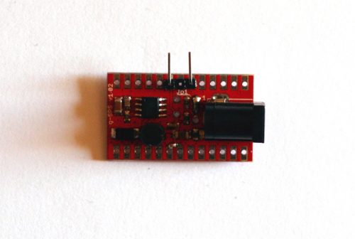
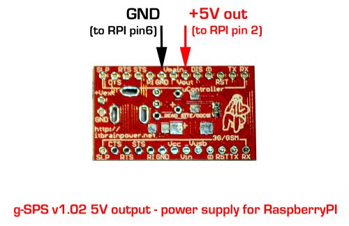
Remove the central pin from the pin-header using the pliers or the clip. Solder the pin-header (see the two pictures above). Solder the barrel connector (optional, see "Barrel jack alternative" later). Check for short-circuits!Wire the boards together
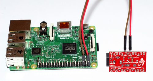
Connect the wires as shown in the above picture. Double check the polarity! You are ready. Enjoy! HINTS:- Barrel jack alternative - you can use 2pin standard 0.1"(2.54 mm) soldered to the +Vext and GND pads, as input power source connector. See details on g-SPS references.
- Increase the stability for bigger current loads - you may use one 1000uF/6.3V lowESR electrolytic capacitor. Bend the capacitor terminals to 90degree, insert it(from the top side)) to the "+" and "GND" [placed just above the "+" hole marking] vias/holes and solder it. (reference: "g-SPS 5V version, back side" picture above)
Thanks for helping to keep our community civil!
Notify staff privately
You flagged this as spam. Undo flag.Flag Post
It's Spam
This post is an advertisement, or vandalism. It is not useful or relevant to the current topic.
This post is an advertisement, or vandalism. It is not useful or relevant to the current topic.
You flagged this as spam. Undo flag.Flag Post


