

New Lynxmotion Smart Servos (LSS) Modules

We have some good news for fans of the Lynxmotion Smart Servos (LSS). The LSS / SES V2 lineup has two new electronic modules: the LSS-2IO Arduino Compatible Board and the LSS-5VR, 2A Regulator Board. Both of these modules are meant to be daisy-chained on the LSS bus and will add extra functionality for LSS users, allowing for the construction of an even wider variety of robotic platforms.
LSS-2IO Arduino-Compatible Board
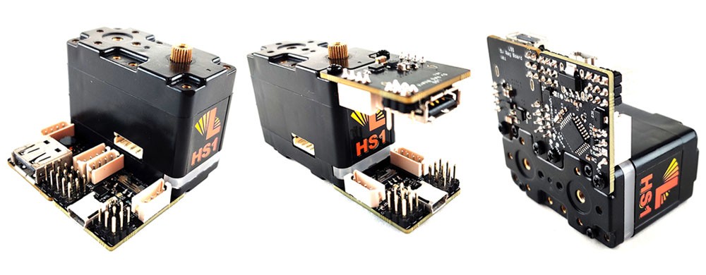
The first module is the LSS-2IO Arduino-Compatible Board which can be used as a multi-purpose I/O, Arduino programmable board and USB-to-Serial adapter. This module is based on the famous ATMega328P MCU with three digital I/O pins (D9, D10 and D11) and three analog input pins (A3, A4 and A5) broken out. It also has two LSS connectors (daisy-chained with Lynxmotion Smart Servos and other SES V2 electronics), an on-board RGB LED (to add some stylish visual effects or messages to your project), a CH340E USB-to-Serial adapter chip and two 5V regulators to power the microcontroller and analog pins.
The 2IO Board has three communication modes: 2RC (as shipped), Arduino and Direct. The mode is easily selected using an on-board switch but is also dependent on the Arduino code running in the ATMega328P chip:
2RC Mode (as shipped with sample code)
In this mode, with the right sketch / code (loaded by default), the 2IO board behaves as a "slave" device that can be daisy-chained on the LSS bus allowing for control of multiple RC servos and sensors through serial commands from the LSS Communication Protocol. This means that you can easily add RC servos and/or analog sensors to an LSS bus and send LSS compatible serial commands to the 2IO to control these RC servos and/or query analog sensors. Note that the 2IO cannot power RC servos directly; they need to be powered from either a separate power source, or using the LSS-5VR module below.
Arduino Mode
In this mode, the 2IO Board acts as a "master", or an Arduino-based robot controller / "robot brain" that can send commands on an LSS bus to control LSS servos. In Arduino mode, you can load the 2IO board with any Arduino program / sketch via the Arduino IDE. This module allows your creation to have on-board "intelligence" as well as allowing analog/digital inputs / outputs so that your robots can have "eyes" (rangefinders, IR sensors, etc..), "ears" (sound sensors), "touch" (force / pressure sensors) and other "senses".
Direct Mode
In this mode, the LSS 2IO Board acts as a USB-to-Serial (UART) converter allowing for control of Lynxmotion Smart Servos (LSS) from a USB device (computer, Raspberry Pi, etc..).
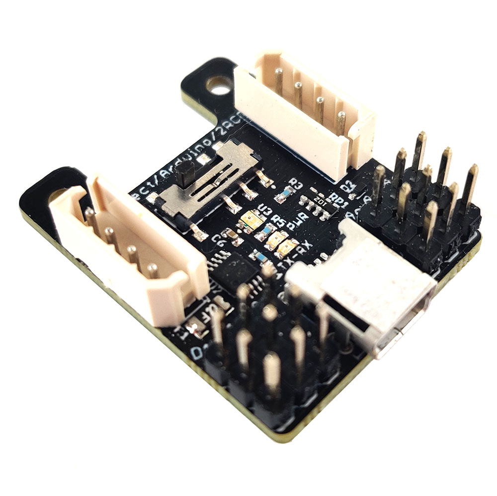
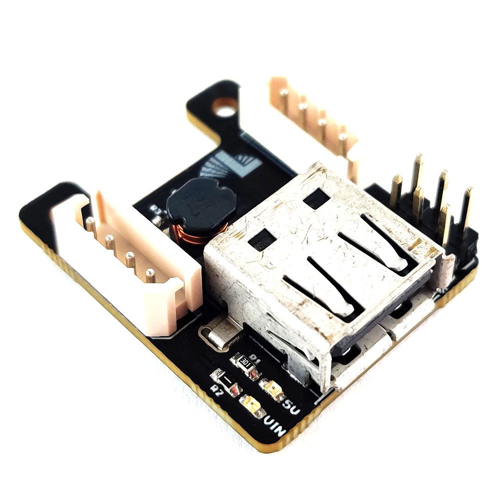
LSS 5VR
The second module is called the LSS 5VR. This board provides a regulated output of 5V (5.3V unloaded) at up to 2A from a 6.5V to 12.6V input via the LSS bus. It can be used to power external 5V devices such as RC servos, sensors and/or USB powered devices. Therefore, if you have 5V devices in your LSS / SES V2-based robotic creation and you need to power them, this module is the way to go.
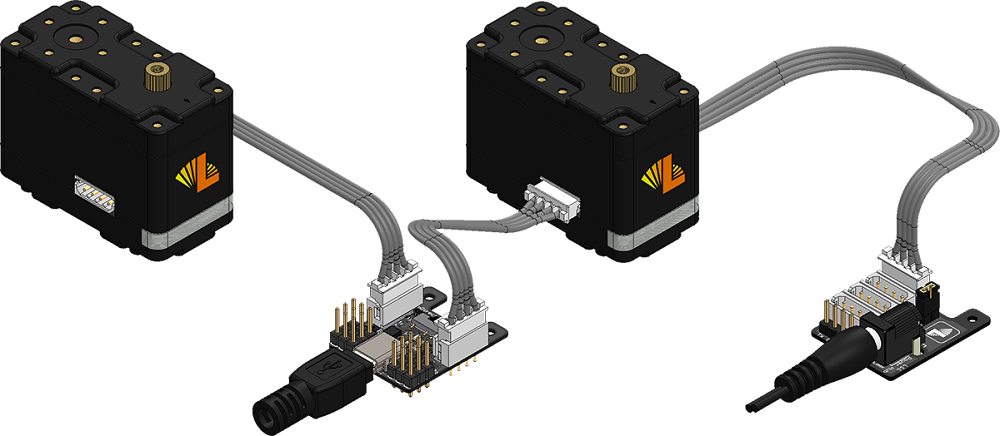
Mounting
The LSS-2IO and the LSS-5VR board have the same form factor as the LSS Power Hub. This form factor allows you to mount one or several of these modules on an LSS as shown below :
Project Example
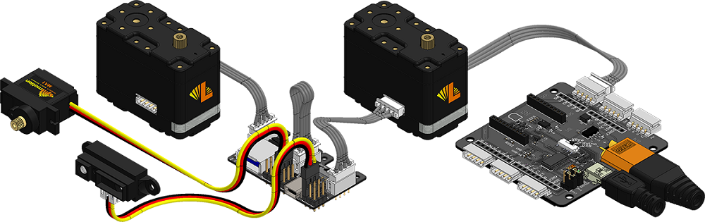
The versatility of the 2IO adds new possibilities to LSS / SES V2 based projects. The following project shows an example of the 2IO and the 5VR. Here is the BOM :
- 2x 2IO Arduino Compatible Boards (1x 2IO in 2RC mode and 1x 2IO in Arduino mode)
- 1x 5V, 2A Regulator Board
- 1x Power Hub
- 1x LSS Standard ST1
- 1x Hitec HS-645MG RC Servo
- 1x Sharp GP2Y0A21YK0F IR Range Sensor
- 1x SPDT Switch
- 1x 12V Power Supply
All the devices in this project are powered via the 12V power supply through the LSS Power Hub. An Arduino sketch is running on one LSS-2IO (in Arduino mode). The example operates in two modes, selectable via the SPDT switch:
MODE 1: "Mimic". The Hitec HS-645MG RC servo is connected to a 2IO module (in 2RC mode) which mimics / copies the motion of the LSS ST1. The 2IO board (in Arduino mode) constantly queries the position of the LSS ST1 by sending serial position query commands on the LSS bus (more information on the LSS Communication Protocol can be found here). The LSS ST1's replies are then parsed and sent as angular position commands to the 2IO (in 2RC mode) which is controlling the Hitec HS-645MG servo to the same angle as the ST1. The commands sent to the 2IO-2RC mode are in 2IO Communication Protocol format.
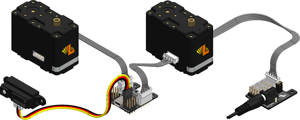
MODE 2: "IR Sensor input". The LSS ST1 and the Hitec HS-645MG rotate proportionally to a linear distance being read by the Sharp GP2Y0A21YK0F IR Range Sensor. The 2IO (in Arduino mode) constantly queries the distance read by the Sharp IR sensor which is connected to the 2IO (in 2RC mode) on A3 pin by sending analog query commands on the LSS bus. The 2IO (in 2RC mode) replies are parsed and sent as position commands (by the 2IO in Arduino mode) to the LSS ST1 and the 2IO (in 2RC mode) that controls the Hitec HS-645MG servo.
The Arduino sketch for this project is available through this Github repo and can be downloaded here.
For more information on these two modules, please visit the LSS 2IO Arduino Compatible Board Wiki Page and the LSS 5V, 2A Regulator Board Wiki Page
Here is the video of the project :
Thanks for helping to keep our community civil!
This post is an advertisement, or vandalism. It is not useful or relevant to the current topic.
You flagged this as spam. Undo flag.Flag Post
Your post is currently under review by our moderation team. The review process usually takes up to 48 business hours.
You can track your post's status in the "My Content" section of your profile. Once approved, it will be published and visible to others.

Thank you for contributing to our community!