IOT temperature logger with GSM transmission and 1wire sensor

Learn how to build your own IoT temperature logger with data uploaded to the cloud. This project uses itbrainpower.net dual SIM full-size GSM shield [a-gsmII] for data transmission (or itbrainpower.net dual SIM full-size GSM GNSS shield [b-gsmgnss]) and Dallas/Maxim 18B20 1wire temperature sensor.
Required time:
- 30-45 minutes - hardware side
- 30-60 minutes for software and cloud setup.
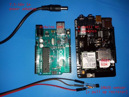
IoT hardware - Bill of Materials
- Arduino UNO,
- a-gsmII v2.105 - Arduino GSM Shield [dual SIM, integrated antenna + uFL, quad-band GSM/GPRS/DTMF/SMS], or
- b-gsmgnss v2.105 - Arduino GSM GPS Shield [dual SIM, integrated antenna + uFL, quad-band GSM/GPRS/DTMF/SMS, Bluetooth 3.0, GNSS (GPS+GLONASS)],
- A 1WIRE temperature sensor - I use DALLAS/MAXIM 18B20
- 8.2kb resistor
- 2G SIM card [with data plan enabled]
- some connecting wires
- 7.5-16V [12V recommended] 1A power source having UNO compatible power jack
About GSM shields used in this project
We're using the new a-gsmII v2.105 (Arduino full size GSM shield), together with b-gsmgnss v2.105 (Arduino full size GSM + GNSS (GPS + GLONASS) shield). They're both Arduino, Teensy, BeagleBone & Raspberry Pi compatible shields. They belong to the next generation of the successfully a-gsm v2.064 and offers to best market performances in their product class, and are offered at a reasonable price. In this how-to a-gsmII v2.105 shield is used for representation. The very same hardware settings are applied for b-gsmgnss shield [jumpers and connectors are placed in the same position]. The GSM shields documentation can be found here:Hardware - Step 1 - 18B20 sensor connection details and references
Solder the 8.2kb resistor between "18B20 Vdd" (pin3) and "18B20 DQ/DATA" (pin2). DALLAS/MAXIM 18B20 reference here.Hardware - Step 2 - How to assemble the components together
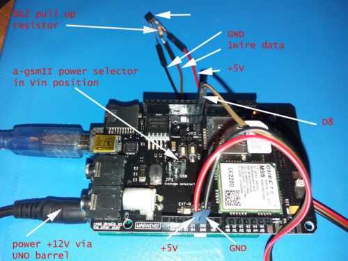
Below, you can see all the IoT components bound together.Here are the wiring steps to follow:
- Solder the Arduino headers to a-gsmII shield
- Plug-in the a-gsmII shield into Arduino UNO
- Set the a-gsmII "Voltage selector" jumper in "Vin" position
- Insert the SIM card in primary SIM socket [a-gsmII/b-gsmgnss - the SIM socket being in the proximity of the PCB]. The SIM must have disabled the PIN-checking procedure (See here for removing PIN check procedure).
- Solder the 8k2 resistor to bw. 18B20 Vdd (pin3)and 18B20 DQ/DATA (pin2).
- Solder the wires to the 18B20 terminals.
- Wire 18B20 Vdd (pin3) to Arduino 5V,
- Wire 18B20 DQ/DATA (pin2) to Arduino D8
- Wire 18B20 GND (pin1) to Arduino GND.
- Connect Arduino UNO USB to your PC
Software - Part 1 - Download packages and set IOT variables
- Download
- either the itbpGSMclass library (beta) "a-gsmII series software IoT REST support for Arduino" from a-gsmII download section
- or "b-gsmgnss series software IoT REST support for ARDUINO" from the b-gsmgnss download section. In order to download "itbpGSMclass", some information is required: the modem's IMEI (marked to the modem, or can be read using AT+CGSN at command) and your email address.
- Expand the archive and install the class and restart the Arduino environment. More details about manual library installing, read Arduino library manual installation.
- Create a folder named agsmII_temperature_Robofun_cloud_logger.
- Download the main code from agsmII_temperature_Robofun_cloud_logger.ino - main code and save it with that name in the folder created in the previous step.
- You'll need to set up some variables in agsmII_temperature_Robofun_cloud_logger.ino: - tempToken (line 19) - replace with the sensor token generated on Robofun Cloud (see below) - samplingPeriod (line 29)
- You'll need to set up some variables in itbpGSMclass library:
- Set SERVER_ADDRESS and SERVER_PORT in itbpGPRSIPdefinition.h for Robofun Cloud #define SERVER_ADDRESS "iot.robofun.ro" #define SERVER_PORT "80"
- Set APN, USERNAME and PASSWORD for your SIM card in itbpGPRSIPdefinition.h
- Choose itbrainpower modem used in itbpGSMdefinition.h, in this example: #define __itbpModem__ agsmII
Software - Part 2 - Cloud setup tasks. Define new sensor. Copy TOKEN data
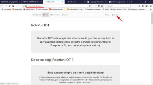
I've chosen Robofun Cloud because it is a very easy-to-use cloud service and the usage it's free of charge. Next, I will guide your steps to set up the cloud service account and sensor.- Create a new account at https://iot.robofun.ro
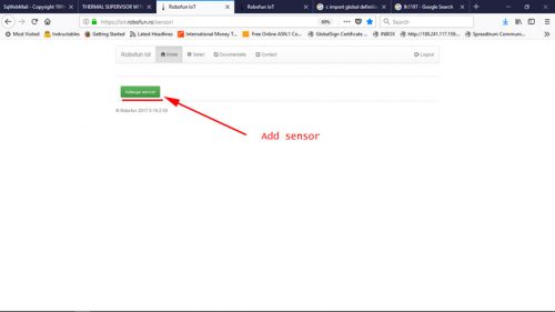
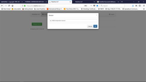
- Create a new sensor
- Chose a name for your sensor
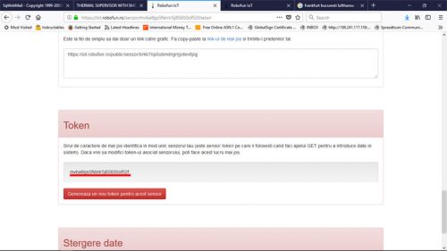
- Scroll down the page to the section named Token
- Copy your sensor Token ID. Use this value for the tempToken variable at line 19 in agsmII_temperature_Robofun_cloud_logger.ino.
How to visualize temperature log records
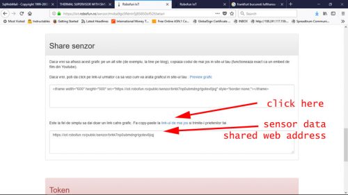
Cloud stored temperature data can be visualized in your cloud sensor page, or in public page.If you want to enable the public page, scroll up the page until "Share sensor" chapter, and follow the link.Congratulations! Your 1 wire temperature data logger is ready!
TUTORIAL PROVIDED WITHOUT ANY WARRANTY - USE IT AT YOUR OWN RISK. Originally written by Dragos Iosub & itbrainpower.net team and published on itbrainpower.netThanks for helping to keep our community civil!
Notify staff privately
You flagged this as spam. Undo flag.Flag Post
It's Spam
This post is an advertisement, or vandalism. It is not useful or relevant to the current topic.
This post is an advertisement, or vandalism. It is not useful or relevant to the current topic.
You flagged this as spam. Undo flag.Flag Post


