

PP2 - PICmicro Processor Unit version 2


Zac Soden details his cheap and simple microcontroller, the Pic Processing Unit or PPU..
A couple of years ago I posted an article on the PPU (see page 2) - a
complete micro-sized PIC16F84 processor board for robot applications.
Since then I have recieved heaps of feedback on the PPU but some recent
requests left me wondering about the integrity of its design. So I sat
down with a new list of features and began work on the PP2. The result
is a much better unit with many more features than the original.
PP2 - PICmicro Processor unit version 2
Cost: < $10
Difficulty: Easy
Power: >5V
Notes: Updated and refined version of the PPU
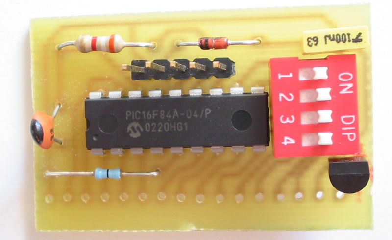
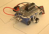
The completed PP2
The PP2 boasts the following features:
- Small size - just 4.5 x 2.6 cm
- In-circuit serial programming connector
- On board 5v, 100mA regulator
- All I/O and power connections brought to a 16 pin header
- Easily obtainable parts (uses R/C oscillator mode)
- Easy to construct
This article will detail complete construction of the PP2 board along
with how to program and use it. Whilst it is easy to buid, you should
not attempt this project without a basic knowledge of electronics. I
will be working to make a kit available some time in the near future.
Quick links:
The Circuit
The PCB
Construction
Testing
Programming
Using the PP2
Appendix 1: Parts List
The Circuit:
The PP2 circuit is quite simple. It features the PIC16F84, voltage
regulator, RC oscillator, ICSP connector (JP1) and IO/Power connector
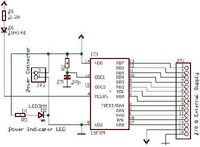
(JP2), as depicted in Schematic 1.
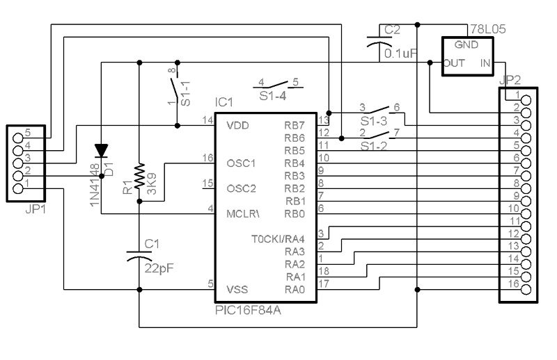
Schematic 1: PP2 circuit (click to enlarge)
The 78L05 voltage regulator IC provides 5 volts to the PICmicro and to
pin 2 of JP2. This can be used to power other circuits from pin 2, so
long as the current drawn doesn't exceed about 90mA. The PIC16F84's
MCLR pin is tied to high via a 1N4148 diode. This allows the 13.5V
programming voltage to be applied to the pin without entering the VDD
line, thus protecting the PICmicro and any other connected components.
An 8 pin DIP switch is included in the circuit to provide isolation
during programming. The switches will need to be set to off whilst the
PP2 is being programmed. The 3K9 resistor and 22pF capacitor act as the
PICmicro's oscillator.
The previous design included an LED
however this was omitted to save board space. Power and ground are
applied on JP2 pins 1 and 16 respectively - the voltage must be between
4.8 and 30 volts.
The PCB:
The PP2 PCB is a compact design which measures just 4.5 x 2.6 cm. It is
single sided and much cleaner than the previous design and whilst it
could be made by hand, I recommend making it photographically. All
parts are through hole types and only one wire link is required (a 0ohm
resistor is best for this).
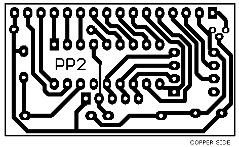
Figure 2: PP2 board artwork (click to download actual size PDF version)
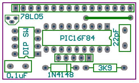
Figure 3: PP2 board layout
Construction:
Construction is very simple. First, mount and solder the resistor,
diode and wire link. The previous design required that the PICmicro be
mounted with a DIP socket and had to be removed for programming. Now,
with the ICSP connector, the PIC16F84 can be soldered in place,
followed by the voltage regulator, capacitors and DIP switch. The last
step is to mount the two pin headers, JP1 and JP2.
Be careful with
component orientation - you should be fine if you follow the board
layout in Figure 3. The DIP switch orientation isn't critical - it can
be placed either way.
Testing:
The first step in testing the PP2 is to check the board over for bad
soldering - dry joints and track bridging. If all looks OK then connect
a 9V battery to the PP2 - positive to Pin 1, negative to pin 16. Ensure
that all of the DIP switches are in the OFF position. Use a multimeter
to check for 5 volts on pin 2 of the main connector (the actual voltage
should lie between 4.9 and 5.1 volts). If you are not getting 5 volts
then check the orientation of the 78L05. If all is well then remove
power and you are ready for use!
Programming:
In order to program the PP2 you will need some kind of PICmicro
programmer capable of programming the PIC16F84. Personally I use a
Microchip PICSTART Plus programmer but for those who can't afford such
extravagant pieces of equipment (I work as a programmer), I recommend
the 'El Cheapo' by Myke Predko - you can find it at Myke's Website.
You will also need to make up a programming cable to connect between
the programmer and the PP2 to allow for ICSP. This is done by simply
soldering a cable to pins 14, 13, 12, 5 and 4 of the programmer's
socket (or making an adapter to plug into it). The other end of the
cable is then terminated with a header plug with the pinout as shown in
the schematic.
Using the PP2:
Using the PP2 is as simple as wiring up to the I/O connector. It can be
soldered into your application, be given a header strip to plug into a
breadboard or any other connection methods you can think of. I/O
connector pins are as follows.
Pin 1: 6 - 18V input
Pin 2: 5V @ 90mA out
Pin 3: RB7
Pin 4: Rb6
Pin 5: RB5
Pin 6: RB4
Pin 7: RB3
Pin 8: RB2
Pin 9: RB1
Pin 10: RB0
Pin 11: RA4
Pin 12: RA3
Pin 13: RA2
Pin 14: RA1
Pin 15: RA0
Pin 16: Ground (-ve)
I hope that the PP2 is useful for your next robot and it works as well for you as it does for me.
| Part | Description |
| R1 | 3K9 ohm Resistor |
| R2 | 0 ohm Resistor (optional) |
| C1 | 22pF Capacitor |
| C2 | 0.1uF Capacitor |
| D1 | 1N4148/1N914 Signal Diode |
| U1 | 78L05 5V, 100mA Voltage Regulator |
| U2 | PIC16F84 or PIC16F84A PICmicro MCU |
| S1 | 4-Way DIP Switch |
| JP1 | 5-Way SIL Pin Header |
| JP2 | 16-Way SIL Pin Header (optional) |
| PCB | PP2 Printed Circuit Board |
Read on to find out about the original PPU
Move over BASIC Stamp; here comes the PPU, a complete, micro sized,
PIC16F84 based microcomputer board. Not only is it easy to make, but
using the freeware JAL compiler, the PIC Processor Unit is also simple
to program. This page contains complete details to make your own PPU.
As I ventured into the world of microcomputers I began to find that all
of the easy, beginner type modules were (and still are!) very expensive
so I decided to purchase a PIC programming kit. The kit included a
PIC16F84, programming hardware and the programming software/ compiler.
I hit a very dead end as soon as I had finished constructing the kit; I
had to build up the "core" PIC circuit on a breadboard in order to test
the demo program provided (not so hard), and I couldn't write any
programs (near-impossible).
 |
So in June 2001 I decided to create the PPU: a small BASIC stamp type
microcomputer board which contained the minimal "core" components
required to make the PIC run and made use of the thirteen I/Os a lot
more straightforward.
Quick links:
The Circuit
The Board
Programming Hardware
JAL: (Not)
Using the PPU
The Circuit:
The PIC16F84 seemed to be a good choice of microcontroller for a number of reasons:
- 13 I/O lines
- Cheap
- Easily obtainable
- Small
- Substantial for learning microcontroller basics
In
order to run, the PIC16F84 requires three things: power (duh!), the
MCLR pin pulled high and appropriate external clock components. The
resulting circuit can be seen in Fig 1.
Because the PIC16F84 will accept a wide supply voltage range, a voltage
regulator was omitted in order to keep the board small. If regulated
voltage is required, a seperate power supply circuit will need to be
constructed. Although I could have gained an accurate timing mechanism
by the use of a crystal oscillator, I opted for a resistor-capacitor
clock as correct frequency crystals can be hard to obtain.
Unlike
many other easy PIC microcomputer designs, the PPU allows use of all 13
I/O lines. This is possible by mounting the PIC into the board using a
DIL socket. When programming, the PIC is removed from the PPU and
placed into the programming hardware. All I/O lines and the power
supply rails are brought to a 15 pin header plug (or socket) to allow
easy access to these pins. A power on status LED is provided to give
indication of when the power is on (this function is not as stupid as
it sounds and can be very handy during trouble shooting!)
Fig.2: PPU Prototype PCB. Note that the copper tracks are on the wrong side of the board
The PPU board was designed using the EAGLE Layout Editor 4.01 and
supports all functions described in the previous section. Fig 2 depicts
the board artwork. The red tracks are actually wire links between
components (if using a single sided board).
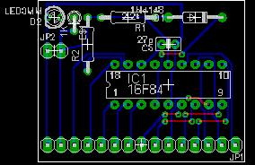
Fig.3: PPU board artwork. View from component side
Note that you must flip the artwork in order to get the copper side
pattern. Althought you can transfer the design by hand (this method was
done for the prototype), it would be a lot better to use photographic
methods to create the PCB.
I acquired the programming hardware, software and the PIC16F84 as a kit
for A$50 from Jaycar Electronics but many other electronics stores sell
them at varied prices. Many of the more expensive kits include a
testbed and should only be purchased if you want to do further
experiments into the PICs functions.
There are also many good sites
on the net where you can get plans to make your own programmer. I
strongly suggest that you buy a kit programmer as it will come with all
required parts. If using a circuit from the net, be sure that you
construct one that comes with accompanying software or it could be a
long exercise trying to get the hardware synchronised with it.
After a heap of frustration, I eventually gave up trying to write a
program in assembly language. In an effort to find an easy way to
program the PPU, I ran to the internet and began searching. The first
program that I found was called the PIC Basic compiler. It wasn't very
long until I discovered the price of the program and I scurried off
with my tail between my legs if you are prepared to pay the expensive
price, it would be worth the money but, being a bit of a stinge, I kept
on searching. After another 10 minutes of so I discovered JAL; a
freeware compiler which utilised a C type language structure.
JAL can be downloaded at the JAL homepage.
At first, I was just really happy to have found a free compiler with an
easy language to learn but it wasn't until later that I discovered its
potential for robotics. JAL, it turns out, is structured perfectly for
robotics. It utilises a very useful include file system which allows
whole blocks of code to be executed with a simple command. In order to
use JAL with the PPU, a couple of the libraries have to be changed to
deal with the resistor-capacitor oscillator.
Follow the
instructions on the JAL site to download and install all of the files
and then unzip jal_libry into the lib folder in the JAL directory. Note
that because we are not using a crystal oscillator, the timings
specified in jdelay are incorrect. Be sure to include 16f84_4 as the
target configuration as its delay timings are closer than those of
16f84_10.
Here is a sample program in JAL code which demonstrates just how simple the language is.
-- Sample program which flashes an LED on pin RA0
-- target configuration: 16f84.
include 16f84_4
-- include the standard library
include jlib
-- configure pin A0 as output
pin_a0_direction = output
-- loop forever
forever loop
-- turn LED on
pin_a0 = on
-- wait ~1 second
delay_1s
-- turn LED off
pin_a0 = off
-- wait ~1 second again
delay_1s
-- signal the loop point
end loop
Once the program has been written, it is saved as a .jal file. To
compile it, drag the file onto the jal.exe icon and, if the libraries
are in the right place and your code is right, jal.exe will produce a
HEX and an ASM file. The HEX file can then be sent off to the
programming software to be downloaded onto the 16F84.
To test the PPU, download the above LED flashing program into the
PIC16F84. Connect the positive leg of and LED to pin RA0 (3rd from the
left on the PPU I/O connector) and the negative leg to ground via a 1K
resistor (leftmost pin on the PPU. Apply around 5V (4.5 to 6 volts
works fine) to the PPU's power lines and the power indicator LED should
light (if not, check both the power indicator LED and power supply's
polarity). If all is well, the LED connected to RA0) should start
flashing at around 1Hz.
You are now ready to go on to more
powerful applications with your PPU. Flashing an LED is just the
beginning; the PPU can handle up to 13 I/O for motors, buzzers, sensors
and all kinds of robotic functions.
Thanks for helping to keep our community civil!
This post is an advertisement, or vandalism. It is not useful or relevant to the current topic.
You flagged this as spam. Undo flag.Flag Post
Your post is currently under review by our moderation team. The review process usually takes up to 48 business hours.
You can track your post's status in the "My Content" section of your profile. Once approved, it will be published and visible to others.

Thank you for contributing to our community!