

How to Make an Internet-Connected Lock: The GO-Lock

We had the pleasure to sponsor a very interesting school project that targeted a real-world problem. These two smart students developped their own connected lock and are sharing today the story of their project.
Who are we?
We are Nathan Hampton and Quinn Sulejmani. Two Engineering Design and Development students at the Career and Technical Center in Frisco, Texas.
What problem is our project trying to solve
Security Instruments Corp. reported that in 2014, 35.2% (504,000) of home burglaries across U.S. suburbs and apartments were considered walk-in burglaries. A walk-in burglary essentially consists of an unlawful entry, where a burglar enters a home without having to use force to break in. Our project, the GO-Lock, tackles this problem, attempting to reduce the number of walk-in burglaries across the United States.
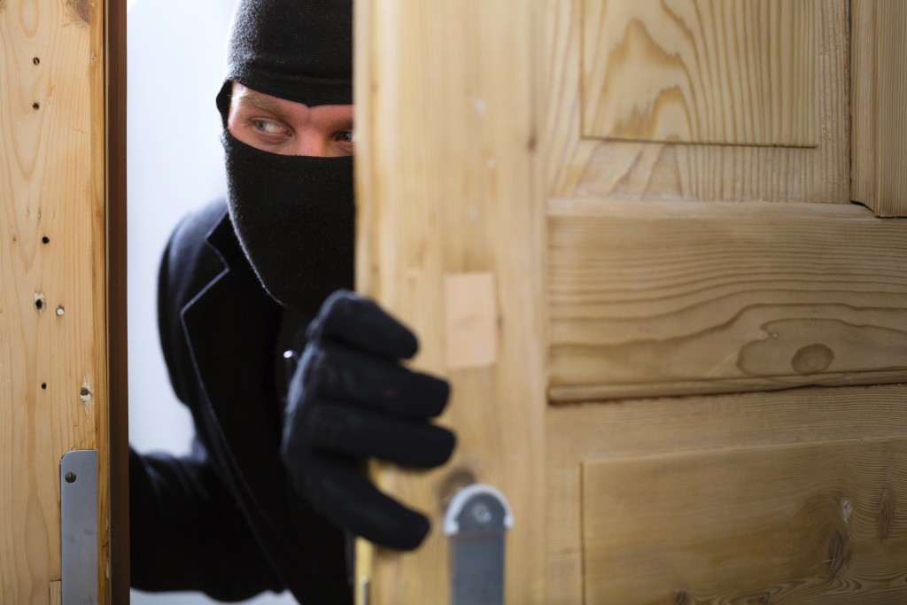 Unlawful entry - Image courtesy of SafeT Systems
Overview of our product : a connected lock
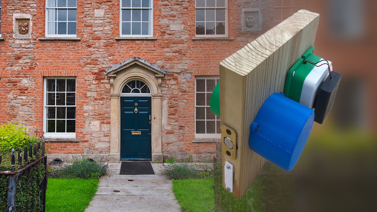
The GO-Lock attempts to decrease this high amount of walk-in burglaries by allowing the user to control access to their home from anywhere via a smartphone. The lock essentially acts as a traditional deadbolt that is powered by electronic components rather than a human hand. It consists of four main pieces of electronics:
 An overview of the product
Functions of each component:
- The magnetic sensor tells the user whether their door is closed or open.
- The potentiometer tells the user whether their door is locked or closed.
- The servo motor turns the deadbolt via a 3D printed axle. When the door is closed, it will lock the door if it is unlocked, or unlock the door if it is locked. When the door is open, the servo will not turn regardless of user input.
- The ESP8266 board acts like the brain of the system. Using code developed by the Arduino Programming IDE, it connects to the user’s smartphone, allowing them to view the outputs of the magnetic sensor and potentiometer, and send an input to the servo motor.
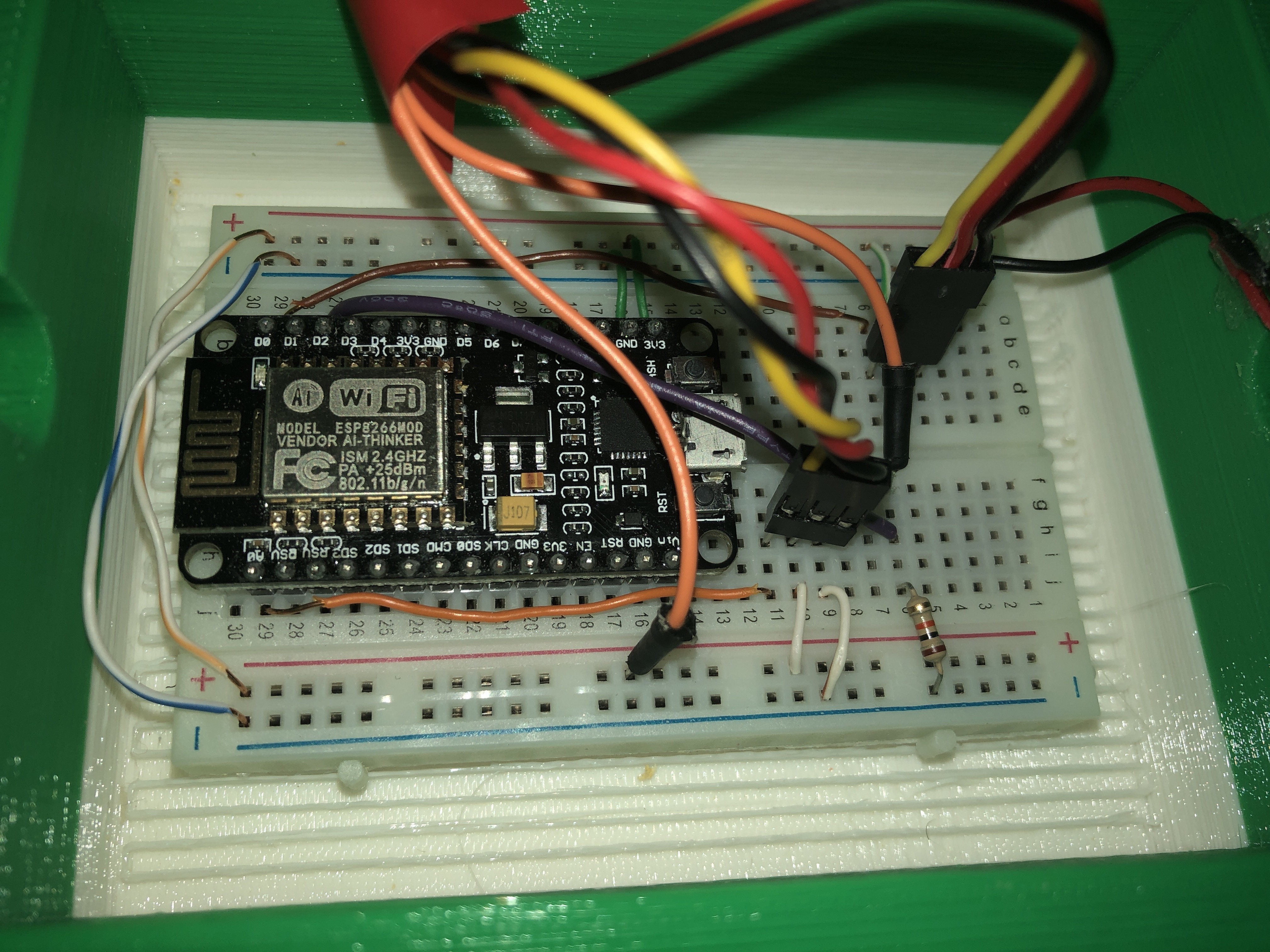 The breadboard with the ESP8266
The first three components are all connected to the ESP8266 via wires and a breadboard. This allows them to receive power from a 6V power supply, and receive or send inputs to the ESP8266. On the other side of the system is the user’s smartphone, which connects to the ESP8266 board via WiFi connection. The smartphone uses an interfaced app that consists of two buttons to toggle the servo and two LEDs: one to display if the door is locked and one to display if the door is closed. The app is provided through the parent-app Blynk, which allows users to create apps to connect to their systems. This app, combined with the lock system attached to their door, allows the user to monitor and control the biggest threat to their home’s safety.
Assembly and Testing
We made the following general observations while testing the GO-Lock:
- When turning clockwise (unlocking door) deadbolt does not return to the position entirely flush with face of door, due to slack inside deadbolt mechanism. Should not be of much issue though.
- Axle and Servo holder did not show any signs of wear after 30 tests (60 servo turns total).
- The magnetic switch has a semi-wide range of detection; does not only output a high value when sensor and magnet are face-to-face.
- The connection between ESP8266 and wireless network can be slightly delayed, as the signal is often choppy.
- The connection between smartphone (Blynk) and ESP8266 is instantaneous.
Conclusion
Throughout the process designing, modeling, building, and testing the GO-Lock prototype, we faced many setbacks and large changes to our overall system. For instance, the learning curve of coding the ESP8266 with Blynk packages was very high and took us nearly a month to fully understand and complete. However, that knowledge allowed us to make quick changes to the electronics side of the system. Additionally, one of our most significant changes to the system was switching from a servo motor casing that could freely rotate, essentially acting like a doorknob for the lock, to a stationary casing that’s sole purpose is to hold the servo in place while it operates. All of these obstacles and altercations to our project ultimately allowed us to refine it with great detail so that it can perform its functions in an efficient manner. The GO-Lock is a plausible solution to prevent walk-in burglaries. Our results from testing show that there are little to no issues or delays turning the servo motor, displaying statuses to the user’s smartphone, and with the connection between the wireless network, the circuit board, and the smartphone. Our final prototype, after various changes to the system, successfully meets the criteria and constraints we set for ourselves at the start of our journey, performing each of its functions how we expected it to.
Special thanks to:
- RobotShop, for donating many of the electronic components used in our project
- Garver Engineering, for providing mentorship throughout the process
- The Career and Technical Education Center
Thanks for helping to keep our community civil!
This post is an advertisement, or vandalism. It is not useful or relevant to the current topic.
You flagged this as spam. Undo flag.Flag Post
Your post is currently under review by our moderation team. The review process usually takes up to 48 business hours.
You can track your post's status in the "My Content" section of your profile. Once approved, it will be published and visible to others.

Thank you for contributing to our community!