

DIY Perimeter Wire Generator and Sensor

Get your own Perimeter Wire Generator and Sensor Soldering Kit here
Background
Wire guidance technology is widely used in the industry, particularly, in warehouses where handling is automated. The robots follow a wire loop buried in the ground. An alternating current of relatively low intensity and frequency between 5Kz and 40KHz flows in this wire. The robot is equipped with inductive sensors, usually based on a tank circuit (with a resonance frequency equal or close to the frequency of the generated wave) that measures the intensity of the electromagnetic field close to the ground. A processing chain (amplification, filters, comparison) makes it possible to determine the position of the robot within to the wire. These days, perimeter/boundary wire is also used to create “invisible fences” to keep pets within yards, and robot lawn mowers within zones. LEGO also uses the same principle to guide vehicles along roads without visitors seeing any lines. For example, here is a video of the Robomow RS630 in action :
This tutorial explains in an easy and intuitive way to help you understand the theory, design, and implementation to make your own generator and sensor for a perimeter wire. The files (Schematics, Eagle Files, Gerbers, 3D Files and Arduino Sample Code) are also available for download. This way, you can add the wire perimeter detection feature to your favorite robot and keep it within an operating "zone". How cool is that!
Generator
Theory
The perimeter wire generator circuit will be based on the famous NE555 timer. NE555 or more commonly called 555 is an integrated circuit used for timer or multivibrator mode. This component is still used today because of its ease of use, low cost, and stability. One billion units are manufactured per year. For our generator, we will use the NE555 in Astable configuration. The stable configuration allows using the NE555 as an oscillator. Two resistors and a capacitor make it possible to modify the oscillation frequency as well as the duty cycle. The arrangement of the components is as shown in the schematic below. The NE555 Generates a (rough) square wave which can run the length of the perimeter wire. Referring to the NE555 datasheet for the timer, there is a sample circuit, as well as the theory of operation (8.3.2 A-stable operation). Texas Instruments is not the only manufacturer of NE555 ICs, so should you choose another chip, be sure to check its manual. We do offer this nice 555 Timer Soldering Kit that will give you the opportunity to solder all the internal components of a 555 timer in a through hole package to allow you to understand the operation of this circuit in detail.
Schematic and Prototyping
The schematic provided in the NE555 manual (8.3.2 A-stable operation section) is fairly complete. A few additional components were added and discussed below. 
NE555 Circuit for A-stable Operation
The formula used to calculate the frequency of the output square wave is :
f = 1.44 / ((Ra+2*Rb)*C) (1)
The frequency range of the generated square wave will be between 32Khz and 44KHz which is a specific frequency that shouldn't interfere with other close devices. For this, we have chosen Ra = 3.3KOhms, Rb = 12KOhms + 4.7KOhms Potentiometer and C = 1.2nF.
The potentiometer will help us vary the frequency of the square wave output to match the resonance frequency of the LC Tank circuit that will be discussed later on. The theoretical lowest and highest value of the output frequency will be as follows calculated by the formula (1) :
Lowest frequency value : fL = 1.44 / ((3.3+2*(12+4.7))*1.2*10^(-9)) ≈32 698Hz
Highest frequency value : fH = 1.44 / ((3.3+2*(12+0))*1.2*10^(-9)) ≈ 43 956Hz
Since that the 4.7KOhms potentiometer never gets to 0 or 4.7, the output frequency range will vary from around 33.5Khz to 39Khz. Here is the complete schematic of the generator circuit : 
Eagle Generator Schematic
As you can see in the schematic, few additional components were added and will be discussed below. Here is the complete BOM :
- R1 : 3.3 KOhms
- R2 : 12 KOhms
- R3 (Current limiting resistor): 47 Ohms (needs to be fairly large to dissipate heat with a 2W power rating should be enough)
- R4 : 4.7 KOhm potentiometer
- C2,C4 : 100nF
- C3 : 1.2nF (1000pF will also do the job)
- C5 : 1uF
- J1: 2.5mm center positive barrel connector (5-15V DC)
- J2 : Screw terminal (two positions)
- IC1: NE555 Precision Timer
Additional parts added to the schematic includes A barrel jack (J1) for easy connection to a wall adapter (12V) and a screw terminal (12) to conveniently connect to the perimeter wire. Perimeter Wire: Note that the longer the perimeter wire, the more the signal degrades. We tested the setup with roughly 100' of 22 gauge multi-strand wire (pegged into the ground as opposed to buried). Power Supply: A 12V wall adapter is incredibly common, and any current rating above 500mA should work well. You can also choose a 12V lead acid or 11.1V LiPo to keep it within the case, but be sure to weatherproof it and turn it off when not in use. Here some parts we offer that you might need when building the generator circuit :
- 2.1mm Barrel Jack to terminal or this 2.1mm Barrel Jack Adapter - Breadboard Compatible
- 400 Tie Point Interlocking Transparent Solderless Breadboard
- 65 x 22 Gauge Assorted Jumper Wires
- DFRobot Resistor Kit
- SparkFun Capacitor Kit
- 12VDC 3A Wall Adapter Power Supply
Here is what the generator circuit should look like on a breadboard : 
Fritzing Generator Breadboard
Results
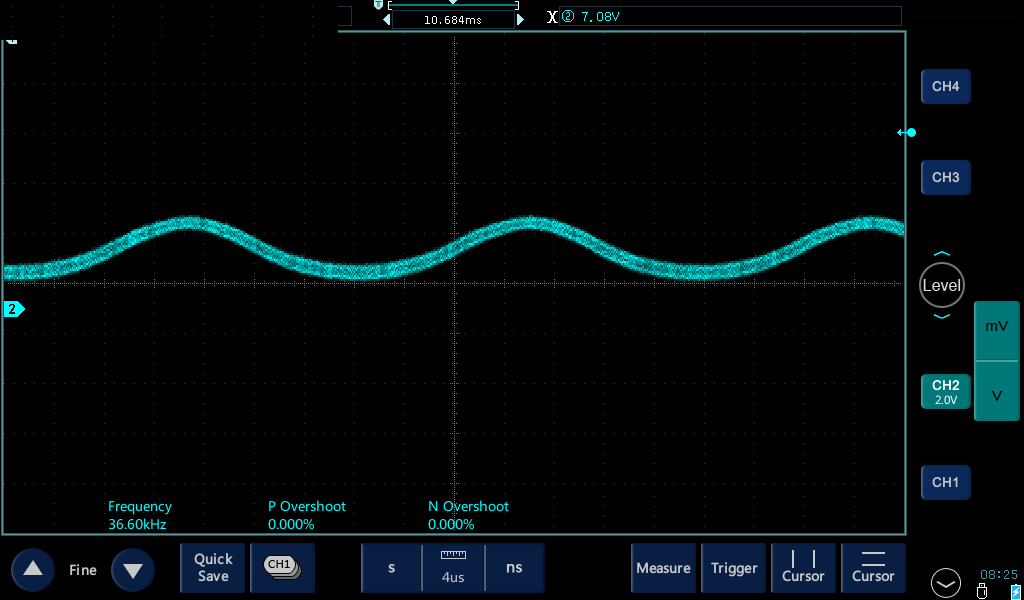
As shown in the below oscilloscope screenshot of the output of the generator circuit (taken with the Micsig 200 MHz 1 GS/s 4 Channels Tablet Oscilloscope), we can see a (rough) square wave with a frequency of 36.41KHz and an amplitude of 11.8V (using a 12V power adapter). The frequency can be varied slightly by adjusting the R4 potentiometer. 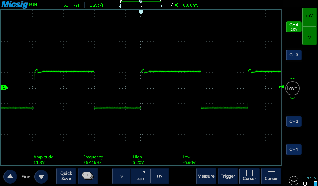
Generator Square Wave Output
A solderless breadboard is rarely ever a long-term solution and is best used to create a quick prototype. Therefore, after confirming that the generator circuit is working as it should, generating a square wave with a frequency range 33.5Khz and 40KHz (variable through the R4 pot), we have designed a PCB (24mmx34mm) only with PTH (Plated-through Hole) components to make it a nice small square wave generator board. Since through-hole components were used for prototyping with a breadboard, the PCB could also use through-hole components as well (instead of surface mount), and allows for easy soldering by hand. Placement of the components is not exact, and you can likely find room for improvement. We have made the Eagle and Gerber files available for download so that you can make your own PCB. Files can be found in the "Files" section at the end of this article. Here is some tips when designing your own board :
- Have the barrel connector and screw terminal on the same side of the board
- Place the components relatively close to each other and minimize traces/lengths
- Have the mounting holes be a standard diameter, and located in an easy to reproduce rectangle.
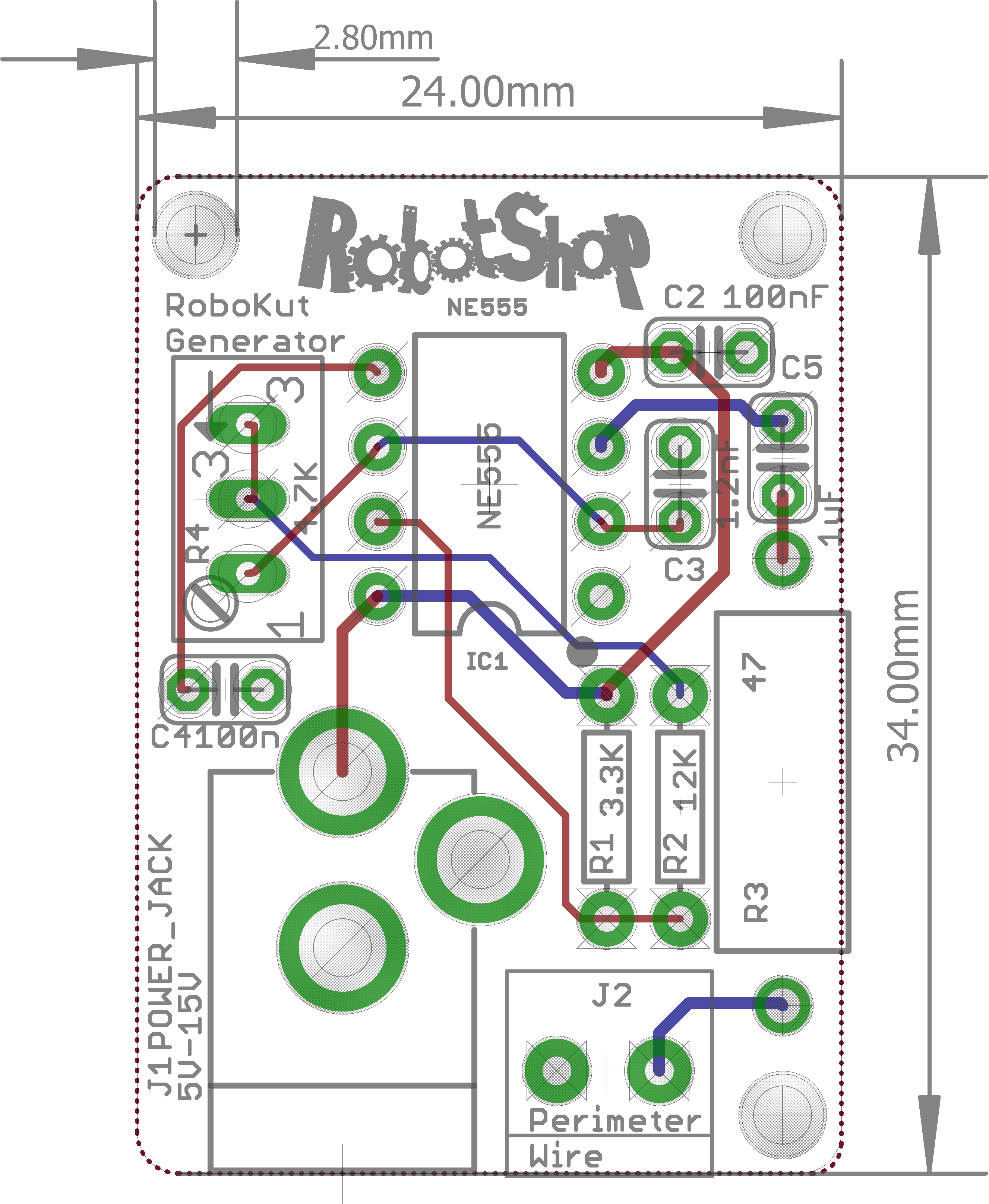
Generator Board Eagle |
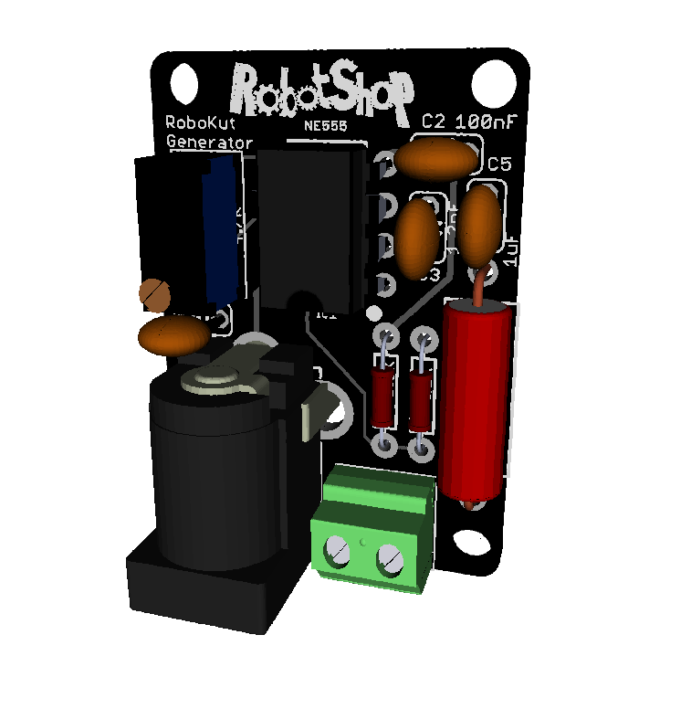 Generator Board 3D Generator Board 3D |
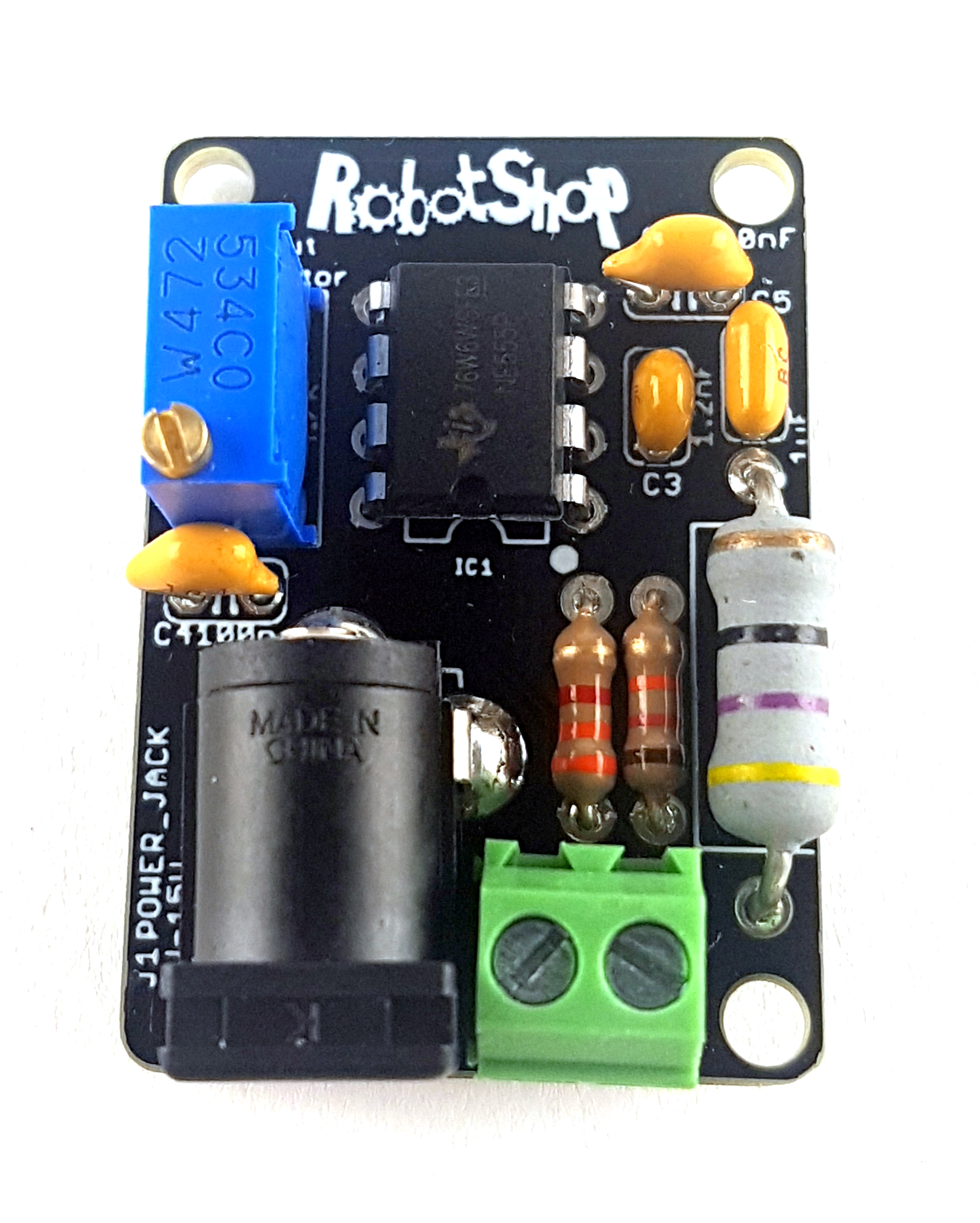 Generator Board Generator Board |
Wire Installation
So how to install the wire? Rather than burying it, it’s easiest to simply use pegs to keep it in place. You’re free to use whatever you want to keep the wire in place, but plastic works best. A pack of 50 pegs used for robot lawn mowers tends to be inexpensive. When laying the wire, be sure to have both ends meet at the same location to connect to the generator board through the screw terminal.
Perimeter Wire Installation 1 |
Perimeter Wire Installation 2 |

Perimeter Wire Installation 3 |
Generator Setup
Weather Resistance
Since the system will most likely be left outside to be used outdoors. The perimeter wire needs a weather-resistant coating, and the generator circuit itself housed in a waterproof case. You can use an Enclosure to protect the generator from rain. Not all wire is created equal. If you plan to leave the wire out, be sure to invest in the correct wire, for example, the Robomow 300' Perimeter Wire Shielding which is not UV / water resistant will degrade quickly over time and become brittle.
Sensor
Theory
Now that we have built the generator circuit and make sure that it is operating as it supposed, it is time to start thinking about how to detect the signal going through the wire. For this, we invite you to read about the LC Circuit, also called Tank Circuit or Tuned Circuit. An LC circuit is an electrical circuit based on an Inductor/Coil (L) and a capacitor (C) connected in parallel. This circuit is used in filters, tuners, and frequency mixers. Consequently, it is commonly used in wireless broadcast transmissions for both broadcast and reception. We won't go into the theoretical details regarding LC circuits, but the most important thing to keep in mind to understand the sensor circuit used in this article, would be the formula for calculating the resonance frequency of an LC circuit, which goes like this:
f0 = 1/(2*π*√(L*C)) (2)
Where L is the inductance value of the coil in H (Henry) and C is the capacitance value of the capacitor in F (Farads).
For the sensor to detect the 34kHz-40Khz signal that runs into the wire, the tank circuit we used should have a resonance frequency in this range. We chose L = 1mH and C = 22nF to obtain a resonance frequency of 33 932Hz calculated using the formula (2).
The amplitude of the signal detected by our tank circuit will be relatively small (a maximum of 80mV when we tested our sensor circuit) when the inductor is about 10cm from the wire, therefore, it will need some amplification. To do so, we have used the popular LM324 Op-Amp amplifier to amplify the signal with a gain of 100 in a non-inverting configuration 2 stages amplification to make sure to obtain a nice readable analog signal at a greater distance than 10cm in the output of the sensor. This article provides useful information about Op-Amps in general. Also, you can have a look at the LM324's datasheet.
Here is a typical circuit schematic of an LM324 amplifier :

Op-Amp in non-inverting configuration
Using the equation for a non-inverting gain configuration, Av = 1+R2/R1. Setting the R1 to 10KOhms and R2 to 1MOhms will provide a gain of 100, which is within the desired specification.
In order for the robot to be able to detect the perimeter wire in different orientations, it is more appropriate to have more than one sensor installed on it. The more sensors on the robot, the better it will detect the boundary wire.
For this tutorial, and since the LM324 is a quad-op amplifier (this means that one LM324 chip has 4 separate amplifiers), we will be using two detecting sensors on the board. This means using two LC circuits and each will have 2 stages of amplification. Therefore, just one LM324 chip is needed.
Schematic and Prototyping
As we discussed above, the schematic for the sensor board is pretty straightforward. It is composed of 2 LC circuits, one LM324 chip, and a couple of 10KOhms and 1MOhms resistors to set the gains of the amplifiers. 
Eagle Sensor Schematic
Here is a list of the components that you can use :
- R1, R3, R5, R7 : 10KOhm Resistors
- R2, R4, R6, R8 : 1MOhm Resistors
- C1, C2 : 22nF Capacitors
- IC: LM324N amplifier
- JP3 / JP4: 2.54mm 3-pin M/M headers
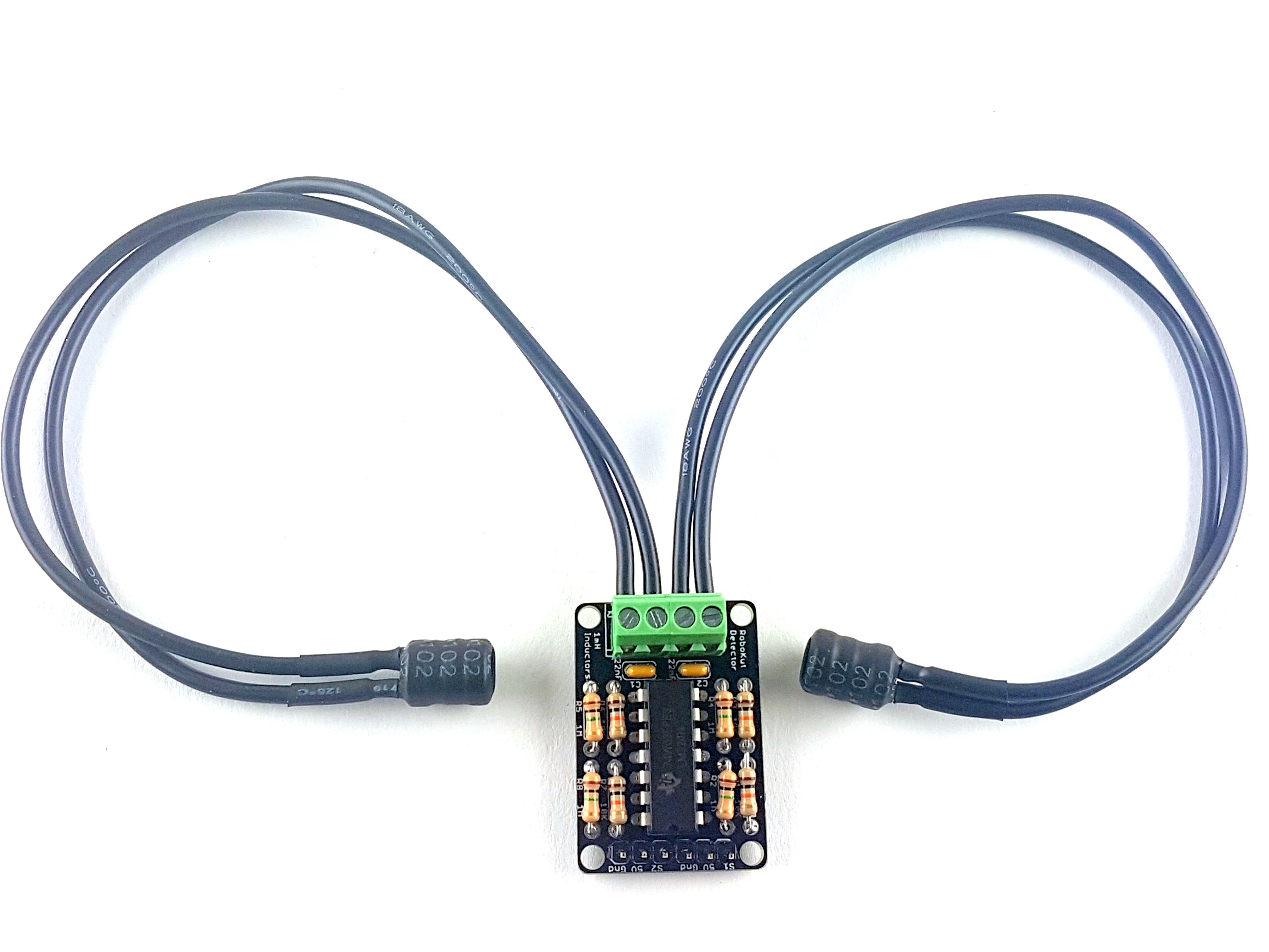
- Inductors 1, 2 : 1mH*
* 1mH Inductors with a current rating of 420mA and a Q factor of 40 @ 252kHz should work well. We have added screw terminals as inductor leads to the schematic in order for the inductors ( with leads soldered to wires) to be placed at convenient locations on the robot. Then, the wires (of the inductors) will be connected to the screw terminals. Out1 and Out2 pins could be directly connected to a microcontroller's analog input pins. For example, you could use an Arduino UNO Board or, better, a BotBoarduino Controller for a more convenient connection as it has analog pins broken-out into a row of 3 pins (Signal, VCC, GND) and it is also Arduino compatible. The LM324 chip will be powered through the microcontroller's 5V, therefore, the analog signal (detected wave) from the sensor board will vary between 0V and 5V depending on the distance between the inductor and the perimeter wire. The closer the inductor is to the perimeter wire, the higher the amplitude of the sensor circuit output wave. Here is what the sensor circuit should look like on a breadboard : 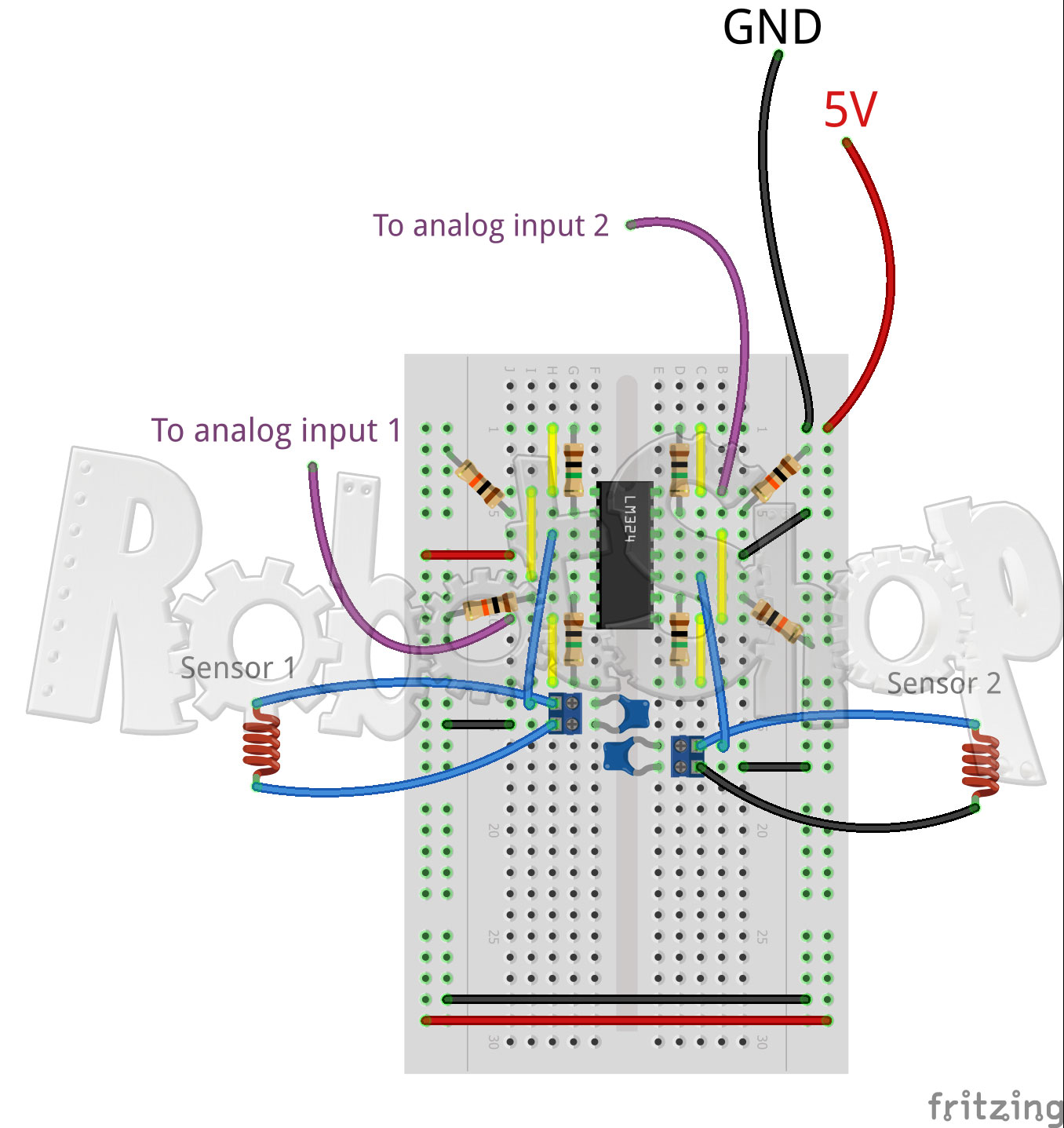
Fritzing Sensor Breadboard
Results
As we can see in the oscilloscope's screenshots below, the detected wave at the output of the LC circuit is amplified and saturates at 5V when the inductor is at 15cm to the perimeter wire :
Tank Circuit Output (Inductor @ 15cm of wire) |
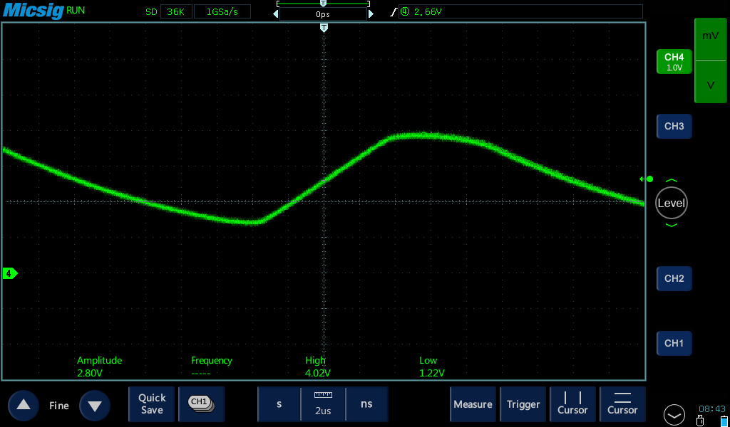
Sensor Circuit Output After Amplification (Inductor @ 15cm of wire) |
Same as we did with the generator circuit, we have designed a nice compact PCB with through-hole components for the sensor board with two tank circuits, an amplifier, and 2 analog outputs. Files can be found in the "Files" section at the end of this article.
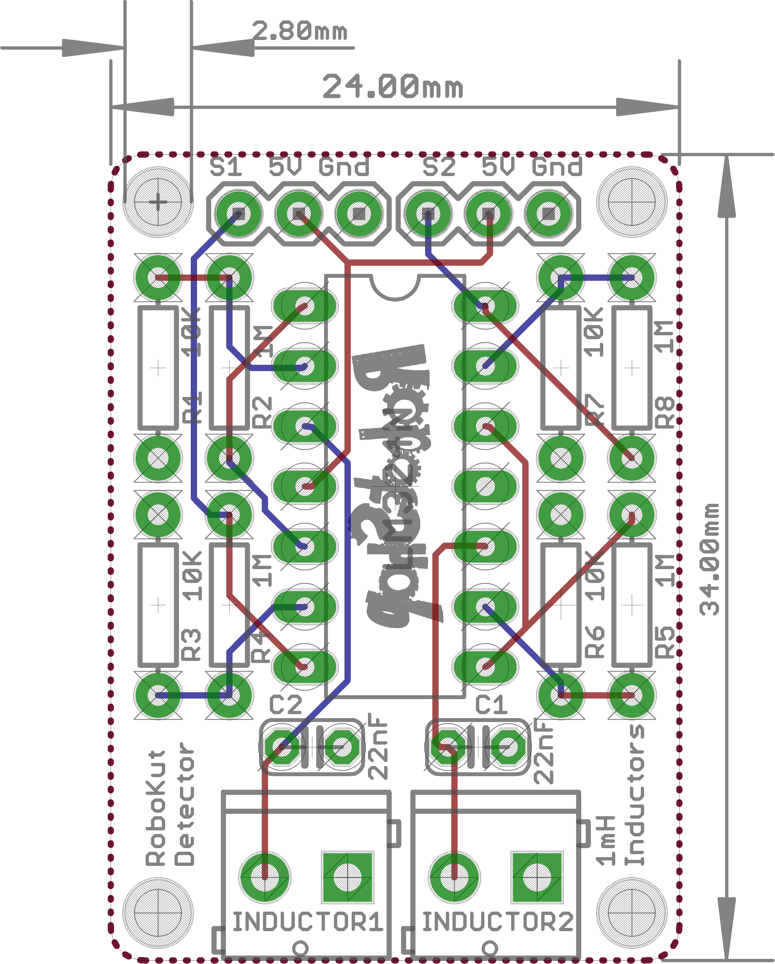
Sensor Board Eagle |
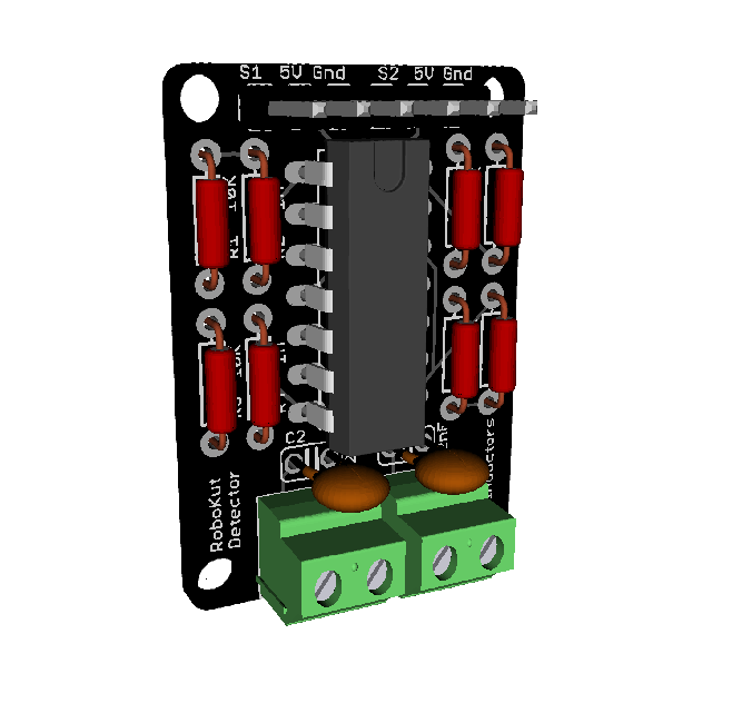
Sensor Board 3D |
 Sensor Board Sensor Board |
Obtaining an optimal detection of the perimeter wire with the inductors of the sensor circuit will depend on how the inductors are placed into the robot. If you use a through-hole radial inductor like we did, the inductor's axis should be perpendicular to the perimeter wire as below : 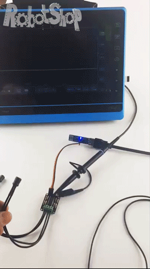
Perimeter Wire Detection
Arduino Code
The Arduino code that you could use for your perimeter wire generator and the sensor is very simple. As the output of the sensor board is two analog signals varying from 0V to 5V (one for each sensor/inductor), the AnalogRead Arduino example can be used. Just connect the two output pins of the sensor board to two analog input pins and read the appropriate pin by modifying the Arduino AnalogRead Example. Using the Arduino serial monitor, you should see the RAW value of the analog pin you are using vary from 0 to 1024 as you approach the inductor to the perimeter wire. 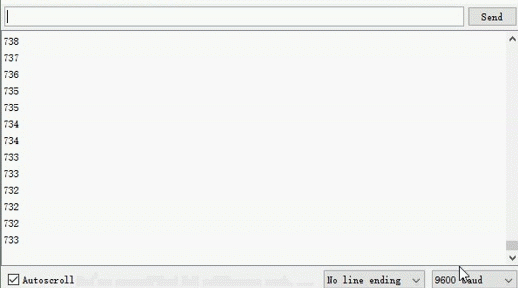
Arduino Analog Read
If you are using the wire perimeter generator and sensor in a robot, you can set a threshold (that will correspond to a distance between the inductor and the perimeter wire) for the robot to get back or turn as soon as this threshold is reached. This way, the robot will keep moving within the delimited zone. So again, how cool is that!
We would be happy to hear about your project on RobotShop's forum. Also, feel free to share your version of the Perimeter Wire Generator and Sensor in the comments section. The RobotShop Perimeter Wire Generator and Sensor Soldering Kit can be purchased here
Thanks for helping to keep our community civil!
This post is an advertisement, or vandalism. It is not useful or relevant to the current topic.
You flagged this as spam. Undo flag.Flag Post
Your post is currently under review by our moderation team. The review process usually takes up to 48 business hours.
You can track your post's status in the "My Content" section of your profile. Once approved, it will be published and visible to others.

Thank you for contributing to our community!